Page 4114 of 5135

05−1 4
−
DIAGNOSTICS SFI SYSTEM (2AZ−FSE)
AVENSIS Supplement (RM 1045E)
Symbols (Terminals No.)
STD Voltage
Condition
Terminal Description
Wiring Color
OC 1+(E 11−1 6)
− OC 1−(E11−1 5)W−G −Y−BCamshaft timing oil con-
trol valve (OCV)Ignition switch ONPulse generation
(See page 05 −41)
EVP 1(E 13− 34) −E0 1(E 13− 7)W −G −W −BVSV for EVAPIgnition switch ON9to 14V
SCV (E 13− 5) −E1 (E 11−1 )L− B −BRVSV for IACVIgnition switch ON9to 14V
PIM (E 13− 33) −E2 (E 13− 28)G −W −BRVacuum sensorIgnition switch ON3.3 to 3.9 V
PIM (E 13− 33) −E2 (E 13− 28)G −W −BRVacuum sensorApply vacuum of 26.7 kPa (200
mmHg, 7.9 in.Hg)2.6 to 3.0 V
PB (E 13− 26) −E2 (E 13− 28)Y −BRBrake booster pressure
sensorIgnition switch ON3.3 to 3.9 V
PB (E 13− 26) −E2 (E 13− 28)Y −BRBrake booster pressure
sensorApply vacuum of 26.7 kPa (200
mmHg, 7.9 in.Hg)2.6 to 3.0 V
PR (E 13− 23) −E2 (E 13− 28)Y −G −BRFuel pressure sensorIdling2.1 to 3.2 V
FP+ (E 12− 6) −E0 1(E 13− 7)
FP −(E 12− 3) −E0 1(E 13− 7)R −BR
G −BRSpill valveIdlingPulse generation
(See page 05 −207)
STA (E 13−1 7)−E1 (E 11−1 )B−Y −BRStarter signalShift position in neutral, Ignition
switch START6.0 V or more
STP (E 10−1 9)−E1 (E 11−1 )G−W −BRStop lamp switchBrake pedal depressed9to 14V
STP (E 10−1 9)−E1 (E 11−1 )G−W −BRStop lamp switchBrake pedal releasedBelow 1.5 V
ST 1− (E10−1 2)−E1 (E 11−1 )G−W −BRStop lamp switchIgnition switch ON, Brake pedal de-
pressedBelow 1.5 V
ST 1− (E10−1 2)−E1 (E 11−1 )G−W −BRStop lamp switchIgnition switch ON, Brake pedal re-
leased7.5 to 14V
W (E9 −11)− E1 (E 11−1 )W−W −BCHK ENGIdling9to 14V
W (E9 −11)− E1 (E 11−1 )W−W −BCHK ENGIgnition switch ONBelow 3.0 V
ELS (E9 −12)−E1 (E 11−1 )G−BRElectric loadTaillight switch ON, Defogger switch
ON7.5 to 14V
ELS (E9 −12)−E1 (E 11−1 )G−BRElectric loadTaillight switch OFF, Defogger
switch OFF0to 1.5 V
TACH (E9 −5) −E1 (E 11−1 )GR−R −BREngine speedIdlingPulse generation
SPD (E 10−1 7)−E1 (E 11−1 )V−W −W −BSpeed signal from com-
bination meterIgnition switch ON, Rotate driving
wheel slowly4.5 to 5.5 V
TC (E9 −20) −E1 (E 11−1 )W−L −BRTerminal TC of DLC 3Ignition switch ON9to 14V
SIL (E9 −18)−E1 (E 11−1 )W−G −BRTerminal SIL of DLC3Connect the hand −held tester to
DLC3Pulse generation
PSW (E 11−10)−E1 (E 11−1 )G−BRPower steering oil pres-
sure switchWhile turning the steering wheelBelow 1.5 V
F/PS (E9 −14)−E1 (E 11−1 )LG−B −BRAirbag sensor assemblyIgnition switch ONBelow 1.5 V
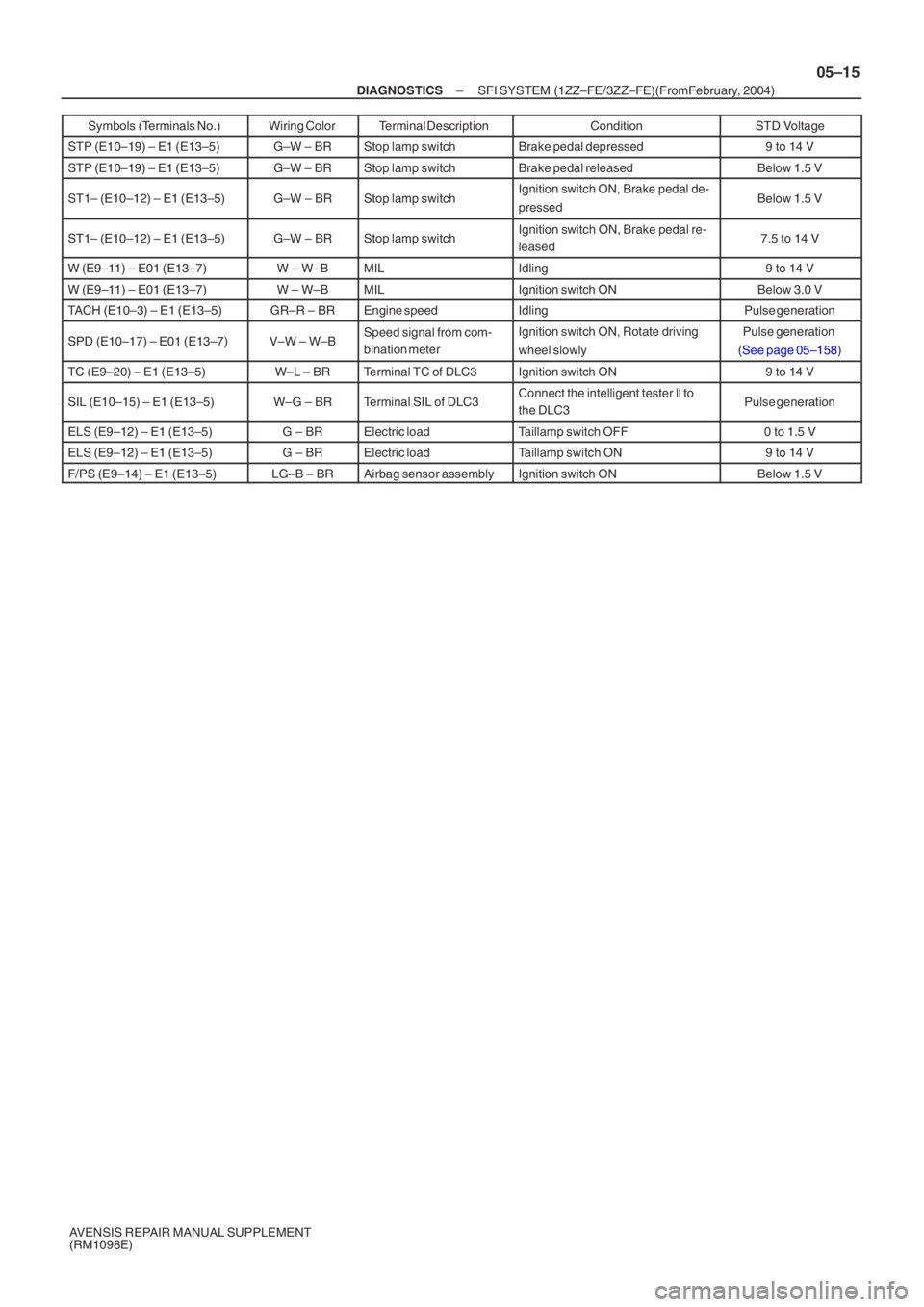
Page 4909 of 5135

–
DIAGNOSTICS SFI SYSTEM (1ZZ–FE/3ZZ–FE)(From February, 2004)
05–15
AVENSIS REPAIR MANUAL SUPPLEMENT
(RM1098E)Symbols (Terminals No.)
STD Voltage
Condition
Terminal Description
Wiring Color
STP (E10–19) – E1 (E13–5)G–W – BRStop lamp switchBrake pedal depressed9 to 14 V
STP (E10–19) – E1 (E13–5)G–W – BRStop lamp switchBrake pedal releasedBelow 1.5 V
ST1– (E10–12) – E1 (E13–5)G–W – BRStop lamp switchIgnition switch ON, Brake pedal de-
pressedBelow 1.5 V
ST1– (E10–12) – E1 (E13–5)G–W – BRStop lamp switchIgnition switch ON, Brake pedal re-
leased7.5 to 14 V
W (E9–11) – E01 (E13–7)W – W–BMILIdling9 to 14 V
W (E9–11) – E01 (E13–7)W – W–BMILIgnition switch ONBelow 3.0 V
TACH (E10–3) – E1 (E13–5)GR–R – BREngine speedIdlingPulse generation
SPD (E10–17) – E01 (E13–7)V–W – W–BSpeed signal from com-
bination meterIgnition switch ON, Rotate driving
wheel slowlyPulse generation
( See page 05–158 )
TC (E9–20) – E1 (E13–5)W–L – BRTerminal TC of DLC3Ignition switch ON9 to 14 V
SIL (E10–15) – E1 (E13–5)W–G – BRTerminal SIL of DLC3Connect the intelligent tester ll to
the DLC3Pulse generation
ELS (E9–12) – E1 (E13–5)G – BRElectric loadTaillamp switch OFF0 to 1.5 V
ELS (E9–12) – E1 (E13–5)G – BRElectric loadTaillamp switch ON9 to 14 V
F/PS (E9–14) – E1 (E13–5)LG–B – BRAirbag sensor assemblyIgnition switch ONBelow 1.5 V
Page 5092 of 5135
B693482 Claws
(B)(B)
B831882 Claws
Stoppers
B806172 Clips
– INSTRUMENT PANEL/METERINSTRUMENT PANEL SUB–ASSY LOWER (From
February, 2004)71–7
AVENSIS REPAIR MANUAL SUPPLEMENT
(RM1098E)
(b) Disengage the 2 claws (B) and remove the instrument
panel register assy No.1.
9. REMOVE INSTRUMENT PANEL REGISTER ASSY NO.2
10. REMOVE GLOVE COMPARTMENT DOOR ASSY
(a) Remove the screw.
(b) Deform the upper part of the glove compartment door
assy to release the stoppers.
(c) Pull the glove compartment door assy upward to remove
it.
11. REMOVE FRONT PILLAR GARNISH LH
(a) Disengage the 2 clips, and remove the front pillar garnish
LH.
12. REMOVE FRONT PILLAR GARNISH RH
HINT:
Use the same procedures for the RH side and LH side.
13. DISCONNECT PASSENGER AIRBAG CONNECTOR (See Pub. No. RM1018E, page 60–29)
Page 5093 of 5135
Page 5098 of 5135
Page 5100 of 5135
710FY–02
71–4– INSTRUMENT PANEL/METERINSTRUMENT PANEL SUB–ASSY LOWER (From
February, 2004)
AVENSIS REPAIR MANUAL SUPPLEMENT
(RM1098E)
INSTRUMENT PANEL SUB–ASSY LOWER (From February,
2004)
PRECAUTION
1. PRECAUTION FOR VEHICLE WITH SRS AIRBAG AND SEAT BELT PRETENSIONER
(a) Some operations in this section may affect the SRS airbags. Prior to performing the corresponding
operations, read the SRS airbag NOTICE.
Page 5101 of 5135

600K8–02
H42769
60–6
– SUPPLEMENTAL RESTRAINT SYSTEMAIR BAG SENSOR REAR LH (From February, 2004)
AVENSIS REPAIR MANUAL SUPPLEMENT
(RM1098E)
REPLACEMENT
HINT:
Use the same procedures for the RH side and LH side.
1. PRECAUTION (SEE PUB. NO. RM1018E, PAGE 60–1)
2. DISCONNECT BATTERY NEGATIVE TERMINAL
CAUTION:
After removing the terminal, wait for at least 90 seconds before starting the operation.
3. REMOVE REAR DOOR SCUFF PLATE LH (SEE PUB. NO. RM1018E, PAGE 73–36)
4. REMOVE REAR SEAT CUSHION ASSEMBLY (FIXED TYPE REAR SEAT) (SEE PUB. NO.
RM1018E, PAGE 72–33)
5. REMOVE REAR SIDE SEAT BACK ASSY LH (SEPARATED TYPE REAR SEAT) (SEE PUB. NO.
RM1018E, PAGE 72–27)
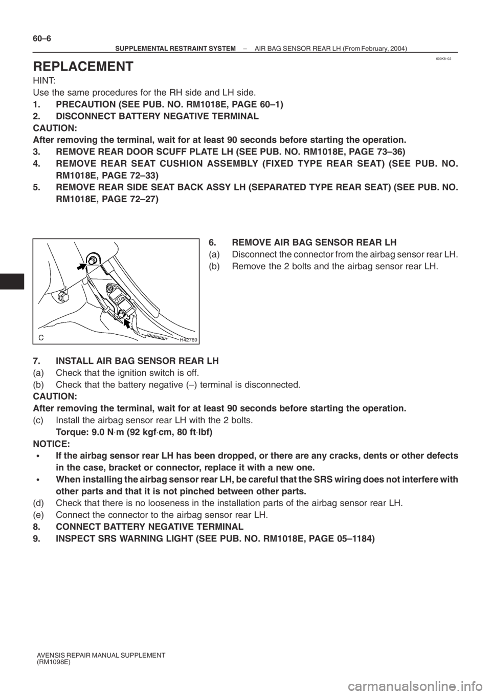
6. REMOVE AIR BAG SENSOR REAR LH
(a) Disconnect the connector from the airbag sensor rear LH.
(b) Remove the 2 bolts and the airbag sensor rear LH.
7. INSTALL AIR BAG SENSOR REAR LH
(a) Check that the ignition switch is off.
(b) Check that the battery negative (–) terminal is disconnected.
CAUTION:
After removing the terminal, wait for at least 90 seconds before starting the operation.
(c) Install the airbag sensor rear LH with the 2 bolts.
Torque: 9.0 N⋅m (92 kgf⋅cm, 80 ft⋅lbf)
NOTICE:
�If the airbag sensor rear LH has been dropped, or there are any cracks, dents or other defects
in the case, bracket or connector, replace it with a new one.
�When installing the airbag sensor rear LH, be careful that the SRS wiring does not interfere with
other parts and that it is not pinched between other parts.
(d) Check that there is no looseness in the installation parts of the airbag sensor rear LH.
(e) Connect the connector to the airbag sensor rear LH.
8. CONNECT BATTERY NEGATIVE TERMINAL
9. INSPECT SRS WARNING LIGHT (SEE PUB. NO. RM1018E, PAGE 05–1184)
Page 5102 of 5135
600K7–02
H42768
Rear Door Scuff Plate LH
Rear Side Seat Back Assy LH
Airbag Sensor Rear LH
9.0 (92, 80 in.⋅lbf)
Rear Seat Cushion Assembly Fixed Type Rear Seat:
Separated Type Rear Seat:
N⋅m (kgf⋅cm, ft⋅lbf) : Specified torque
– SUPPLEMENTAL RESTRAINT SYSTEMAIR BAG SENSOR REAR LH (From February, 2004)
60–5
AVENSIS REPAIR MANUAL SUPPLEMENT
(RM1098E)
AIR BAG SENSOR REAR LH (From February, 2004)
COMPONENTS