Page 636 of 5135
± DIAGNOSTICSECD SYSTEM (1CD±FTV)
05±535
AVENSIS REPAIR MANUAL (RM1018E)
(g) According to the display on tester, perform the ºACTIVE TESTº.
Hand±held Tester DisplayTest DetailsDiagnostic Note
EGR STEP POS
[Test Details]
Change step of EGR motor
Min: 0 step, Max: 125 step
�
TC/TE1
[Test Details]
Connect the TC and TE1
ON or OFF
�
FUEL LEAK TEST
[Test Details]
Fuel leak test
ON or OFF
�
INJECTOR CUT #1
[Test Details]
Injector cut #1
ON or OFF
�
INJECTOR CUT #2
[Test Details]
Injector cut #2
ON or OFF
�
INJECTOR CUT #3
[Test Details]
Injector cut #3
ON or OFF
�
INJECTOR CUT #4
[Test Details]
Injector cut #4
ON or OFF
�
Page 699 of 5135

A81482
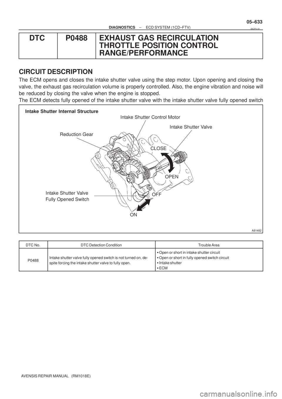
Reduction GearIntake Shutter Control Motor
Intake Shutter Valve
Intake Shutter Valve
Fully Opened Switch Intake Shutter Internal Structure
ON
OFF
CLOSE
OPEN
± DIAGNOSTICSECD SYSTEM (1CD±FTV)
05±633
AVENSIS REPAIR MANUAL (RM1018E)
DTC P0488 EXHAUST GAS RECIRCULATION
THROTTLE POSITION CONTROL
RANGE/PERFORMANCE
CIRCUIT DESCRIPTION
The ECM opens and closes the intake shutter valve using the step motor. Upon opening and closing the
valve, the exhaust gas recirculation volume is properly controlled. Also, the engine vibration and noise will
be reduced by closing the valve when the engine is stopped.
The ECM detects fully opened of the intake shutter valve with the intake shutter valve fully opened switch
DTC No.DTC Detection ConditionTrouble Area
P0488Intake shutter valve fully opened switch is not turned on, de-
spite forcing the intake shutter valve to fully open.
�Open or short in intake shutter circuit
�Open or short in fully opened switch circuit
�Intake shutter
�ECM
05CPV±01
Page 700 of 5135

A81510
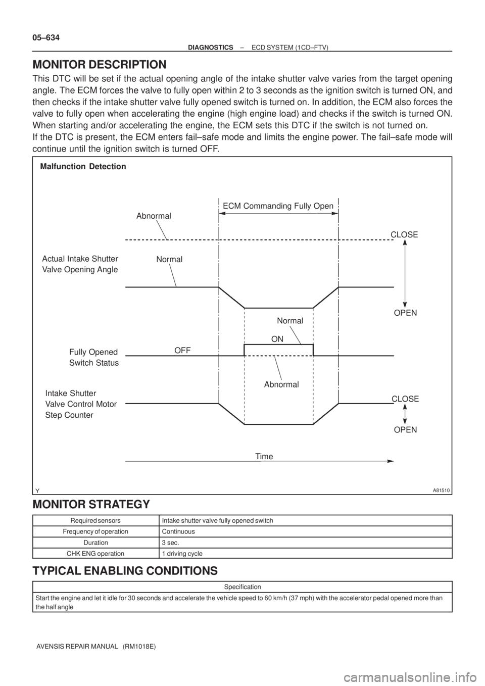
Malfunction Detection
Actual Intake Shutter
Valve Opening Angle
ON
OFF Normal Abnormal
Fully Opened
Switch StatusOPEN CLOSE
Intake Shutter
Valve Control Motor
Step Counter
TimeAbnormal
Normal
OPEN CLOSE ECM Commanding Fully Open
05±634
± DIAGNOSTICSECD SYSTEM (1CD±FTV)
AVENSIS REPAIR MANUAL (RM1018E)
MONITOR DESCRIPTION
This DTC will be set if the actual opening angle of the intake shutter valve varies from the target opening
angle. The ECM forces the valve to fully open within 2 to 3 seconds as the ignition switch is turned ON, and
then checks if the intake shutter valve fully opened switch is turned on. In addition, the ECM also forces the
valve to fully open when accelerating the engine (high engine load) and checks if the switch is turned ON.
When starting and/or accelerating the engine, the ECM sets this DTC if the switch is not turned on.
If the DTC is present, the ECM enters fail±safe mode and limits the engine power. The fail±safe mode will
continue until the ignition switch is turned OFF.
MONITOR STRATEGY
Required sensorsIntake shutter valve fully opened switch
Frequency of operationContinuous
Duration3 sec.
CHK ENG operation1 driving cycle
TYPICAL ENABLING CONDITIONS
Specification
Start the engine and let it idle for 30 seconds and accelerate the vehicle speed to 60 km/h (37 mph) with the accelerator pedal opened more than
the half angle
Page 706 of 5135
A81006
ECM
E3
EGR Valve Assy
G
EG+A 6
E12
Y±G
R±L
G±BE12
E12
E125
4
3EG±A
EG+B
EG±B 6
4
3
1From EFI MAIN Relay
5
2B±W
B±W
B±W
± DIAGNOSTICSECD SYSTEM (1CD±FTV)
05±629
AVENSIS REPAIR MANUAL (RM1018E)
DTC P0400 EXHAUST GAS RECIRCULATION FLOW
DTC P0403 EXHAUST GAS RECIRCULATION CONTROL
CIRCUIT
CIRCUIT DESCRIPTION
DTC No.DTC Detection ConditionTrouble Area
P0400Mass air flow rate is not changed when turning on EGR valve�EGR valve assy
�Open or short in EGR circuit
P0403EGR valve assy motor malfunction
�Oen or short in EGR circuit
�EGR passage
�ECM
WIRING DIAGRAM
INSPECTION PROCEDURE
HINT:
Read freeze frame data using ��� �� ������ �����
� Freeze frame data records the engine conditions when
a malfunction is detected. When troubleshooting, it is useful for determining whether the vehicle was running
or stopped, the engine was warmed up or not, etc. at the time of the malfunction.
05CPU±01
Page 750 of 5135

A71015
0
Accelerator Pedal Opening Angle (deg)125
VPA1 VPA2
5
Movable Range
Usable Range
Usable Range *1
*1
Movable Range
Usable Range
*2
Accelerator pedal released (15�)
Accelerator pedal depressed
(about 100�)
Accelerator Pedal
Position Sensor
Output Voltage (V)
VPA2VPA1 EP2
VCP2
*1:
*
2:
EP1
0.8
105
VCP1*2
*2*1
± DIAGNOSTICSECD SYSTEM (1CD±FTV)
05±675
AVENSIS REPAIR MANUAL (RM1018E)
CIRCUIT DESCRIPTION
HINT:
This electrical throttle system does not use a throttle cable.
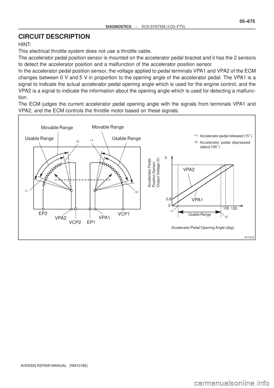
The accelerator pedal position sensor is mounted on the accelerator pedal bracket and it has the 2 sensors
to detect the accelerator position and a malfunction of the accelerator position sensor.
In the accelerator pedal position sensor, the voltage applied to pedal terminals VPA1 and VPA2 of the ECM
changes between 0 V and 5 V in proportion to the opening angle of the accelerator pedal. The VPA1 is a
signal to indicate the actual accelerator pedal opening angle which is used for the engine control, and the
VPA2 is a signal to indicate the information about the opening angle which is used for detecting a malfunc-
tion.
The ECM judges the current accelerator pedal opening angle with the signals from terminals VPA1 and
VPA2, and the ECM controls the throttle motor based on these signals.
Page 786 of 5135

F45132
Battery FL MAINSkid Control ECU
with Actuator
B±G (*1) L (*1)
1 ALT ABS Engine Room R/B No.4 & Engine Room J/B No.4
1
4B
W±BS2
S21 2
+BM
12
1 2
GND1 GND2
S24
W±BW±B
*1: Gasoline
*2: 1CD±FTVEA4
L (*2)
W (*2)
2 12 33 11B1ABS ALT Engine Room R/B No.3Engine Room R/B No.1 &
Engine Room J/B No.1
B (*2)
B±G (*1)
± DIAGNOSTICSABS WITH EBD SYSTEM
05±719
AVENSIS REPAIR MANUAL (RM1018E)
DTC C0273/13 OPEN OR SHORT CIRCUIT IN ABS MOTOR
RELAY CIRCUIT
CIRCUIT DESCRIPTION
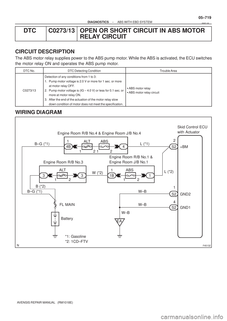
The ABS motor relay supplies power to the ABS pump motor. While the ABS is activated, the ECU switches
the motor relay ON and operates the ABS pump motor.
DTC No.DTC Detecting ConditionTrouble Area
C0273/13
Detection of any conditions from 1 to 3:
1. Pump motor voltage is 2.0 V or more for 1 sec. or more
at motor relay OFF.
2. Pump motor voltage is (IG ± 4.0 V) or less for 0.1 sec. or
more at motor relay ON.
3. After the end of the actuation of the motor relay slow
down condition of motor does not meet the specification.
�ABS motor relay
�ABS motor relay circuit
WIRING DIAGRAM
056ST±06
Page 787 of 5135
F45088GNDGND
+BM
05±720
± DIAGNOSTICSABS WITH EBD SYSTEM
AVENSIS REPAIR MANUAL (RM1018E)
INSPECTION PROCEDURE
HINT:
Start the inspection from step 1 if you are using the hand±held tester and start from step 2 if you are not using
the hand±held tester.
1 PERFORM ACTIVE TEST BY HAND±HELD TESTER(ABS MOTOR RELAY)
(a) Check the operation sound of the ABS motor individually when operating it with the hand±held tester.
OK:
The operation sound of the ABS motor is heard.
OK IF THE SAME CODE IS STILL OUTPUT AFTER
THE DTC IS DELETED, CHECK THE CONTACT
CONDITION OF EACH CONNECTION
NG
2 INSPECT SKID CONTROL ECU CONNECTOR(+BM TERMINAL VOLTAGE)
(a) Disconnect the skid control ECU connector.
(b) Measure the voltage between terminals +BM and GND of
the skid control ECU harness side connector.
OK:
Voltage: 10 to 14 V
OK IF THE SAME CODE IS STILL OUTPUT AFTER
THE DTC IS DELETED, CHECK THE CONTACT
CONDITION OF EACH CONNECTION
NG
Page 802 of 5135

050XB±14
05±704
±
DIAGNOSTICS ABS WITH EBD SYSTEM
AVENSIS REPAIR MANUAL (RM1018E)
DIAGNOSTIC TROUBLE CODE CHART
HINT:
�Using SST 09843±18040, connect the terminal Tc and CG of the DLC3.
�If malfunction is not found when inspecting parts, inspect the ECU and grou\
nd points for poor contact.
�If a malfunction code is displayed during the DTC check, check the circuit\
listed for that code. For de-
tails of each code, refer to the ºSee pageº for respective ºDTC No.º\
in the DTC chart.
�When 2 or more DTCs are detected, perform circuit inspection one by one unti\
l the problem is identi-
fied.
�\f� ��
����
������������ \b���\f������ ���
C0200/31 (05±709)Right front wheel speed sensor signal malfunction� Right front speed sensor
� Right front speed sensor rotor
C0205/32
(05±709)Left front wheel speed sensor signal malfunction� Left front speed sensor
� Left front speed sensor rotor
C0210/33
(05±713)Right rear wheel speed sensor signal malfunction� Right rear speed sensor
� Right rear speed sensor rotor
C0215/34
(05±713)Left rear wheel speed sensor signal malfunction� Left rear speed sensor
� Left rear speed sensor rotor
C0226/21
(05±717)Open or short circuit in ABS actuator solenoid (SFR) circuit� SFRR or SFRH circuit
C0236/22
(05±717)Open or short circuit in ABS actuator solenoid (SFL) circuit� SFLR or SFLH circuit
C0246/23
(05±717)Open or short circuit in ABS actuator solenoid (SRR) circuit� SRRR or SRRH circuit
C0256/24
(05±717)Open or short circuit in ABS actuator solenoid (SRL) circuit� SRLR or SRLH circuit
C0273/13
(05±719)Open or short circuit in ABS motor relay circuit� ABS motor relay
� ABS motor relay circuit
C0278/11
(05±722)Open or short circuit in ABS solenoid relay circuit� ABS solenoid relay
� ABS solenoid relay circuit
C1237/37
(05±725)Speed sensor rotor is wrong number of teeth on one of the 4
wheels� Speed sensor
� Sensor rotor
� Speed sensor circuit
C1241/41
(05±726)Low battery voltage or abnormally high battery voltage
� Battery
� Charging system
� Power source circuit
C1249/58
(05±730)Open circuit in stop light switch circuit� Stop light switch
� Stop light switch circuit
C1300/62
(05±733)Malfunction in skid control ECU� Battery
� Skid control ECU
C1330/35
(05±709)Open circuit in right front speed sensor� Right front speed sensor
� Right front speed sensor circuit
C1331/36
(05±709)Open circuit in left front speed sensor� Left front speed sensor
� Left front speed sensor circuit
C1332/38
(05±713)Open circuit in right rear speed sensor� Right rear speed sensor
� Right rear speed sensor circuit
C1333/39
(05±713)Open circuit in left rear speed sensor� Left rear speed sensor
� Left rear speed sensor circuit
C1350 / 51
(05±735)Pump motor is locked
Open circuit in pump motor ground� Brake actuator pump motor
Always ON
(05±737)Malfunction in ECU
� Battery
� Charging system
� ABS warning light circuit
� Power source circuit
� Skid control ECU