Page 1119 of 5135
C52361
Ts
CGDLC3:
±
DIAGNOSTICS ELECTRONIC MOTOR POWER STEERING SYSTEM
05±1087
AVENSIS REPAIR MANUAL (RM1018E)
INSPECTION PROCEDURE
1INSPECT DLC3 TERMINAL VOLTAGE(Ts TERMINAL) (Ts ± CG)
(a)Turn the ignition switch ON.
(b)Measure the voltage between terminals Ts and CG of
DLC3.
OK:
Voltage: 5 to 16 V
OKGo to step 3
NG
2CHECK HARNESS AND CONNECTOR(DLC3 ± BODY GROUND)
(a)Check for an open or short circuit in harness and connector between terminal \
CG of DLC3 and body ground (See page 01±32).
NG REPAIR OR REPLACE HARNESS ORCONNECTOR
OK
3 CHECK HARNESS AND CONNECTOR(POWER STEERING ECU ASSY ± DLC3)
(a) Check for an open or short circuit in harness and connector between terminal \
Ts of DLC3 and power steering ECU assy (See page 01±32).
NG REPAIR OR REPLACE HARNESS ORCONNECTOR
OK
REPLACE POWER STEERING ECU ASSY(See page 50±20)
Page 1121 of 5135
C52361
TcCGDLC3:
±
DIAGNOSTICS ELECTRONIC MOTOR POWER STEERING SYSTEM
05±1085
AVENSIS REPAIR MANUAL (RM1018E)
INSPECTION PROCEDURE
1INSPECT DLC3 TERMINAL VOLTAGE(Tc TERMINAL)
(a)Turn the ignition switch ON.
(b)Measure the voltage between terminals Tc and CG of
DLC3.
OK:
Voltage: 5 to 16 V
OKGo to step 3
NG
2CHECK HARNESS AND CONNECTOR(DLC3 ± BODY GROUND)
(a)Check for an open or short circuit in harness and connector between terminals\
CG of DLC3 and body ground (See page 01±32).
NG REPAIR OR REPLACE HARNESS ORCONNECTOR
OK
3 CHECK HARNESS AND CONNECTOR(DLC3 ± POWER STEERING ECU ASSY)
(a) Check for an open or short circuit in harness and connector between terminals\
Tc of DLC3 and power steering ECU assy (See page 01±32).
NG REPAIR OR REPLACE HARNESS ORCONNECTOR
OK
REPLACE POWER STEERING ECU ASSY(See page 50±20)
Page 1123 of 5135

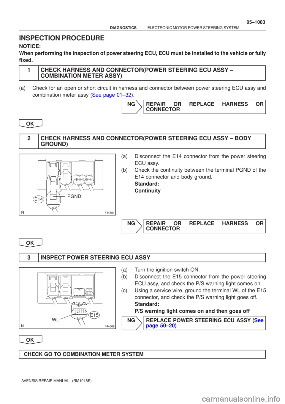
F44851
E14PGND
F44869
E15WL
±
DIAGNOSTICS ELECTRONIC MOTOR POWER STEERING SYSTEM
05±1083
AVENSIS REPAIR MANUAL (RM1018E)
INSPECTION PROCEDURE
NOTICE:
When performing the inspection of power steering ECU, ECU must be instal\
led to the vehicle or fully
fixed.
1CHECK HARNESS AND CONNECTOR(POWER STEERING ECU ASSY ±
COMBINATION METER ASSY)
(a)Check for an open or short circuit in harness and connector between power ste\
ering ECU assy and
combination meter assy (See page 01±32).
NGREPAIR OR REPLACE HARNESS ORCONNECTOR
OK
2CHECK HARNESS AND CONNECTOR(POWER STEERING ECU ASSY ± BODY GROUND)
(a)Disconnect the E14 connector from the power steering
ECU assy.
(b)Check the continuity between the terminal PGND of the
E14 connector and body ground.
Standard:
Continuity
NGREPAIR OR REPLACE HARNESS OR CONNECTOR
OK
3INSPECT POWER STEERING ECU ASSY
(a)Turn the ignition switch ON.
(b)Disconnect the E15 connector from the power steering ECU assy, and check the P/S warning light comes on.
(c)Using a service wire, ground the terminal WL of the E15 connector, and check the P/S warning light goes off.
Standard:
P/S warning light comes on and then goes off
NGREPLACE POWER STEERING ECU ASSY (See page 50±20)
OK
CHECK GO TO COMBINATION METER SYSTEM
Page 1125 of 5135

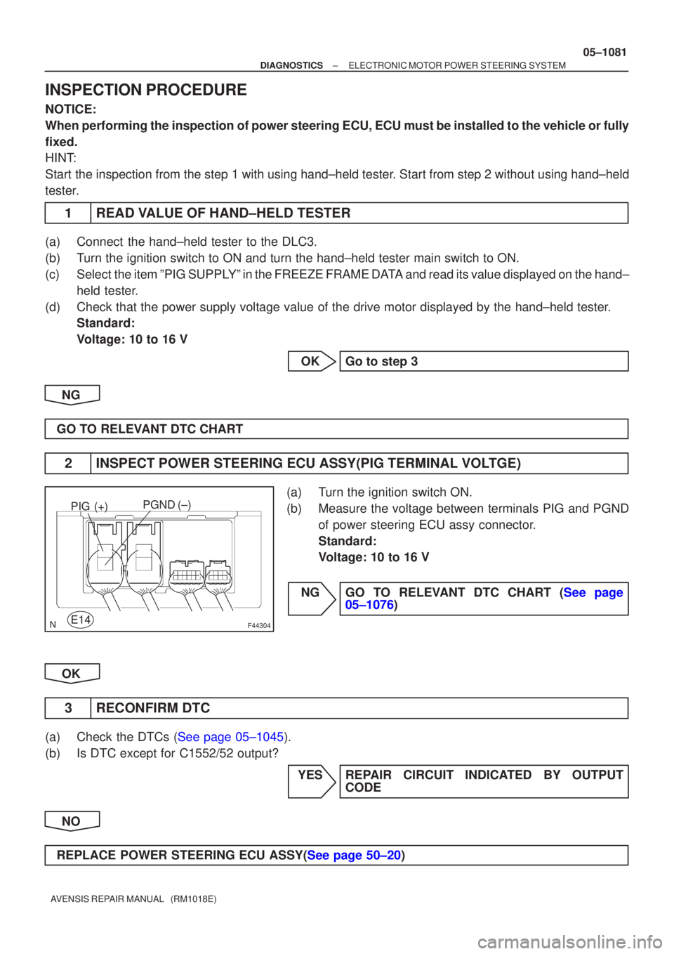
F44304
PGND (±)
E14PIG (+)
±
DIAGNOSTICS ELECTRONIC MOTOR POWER STEERING SYSTEM
05±1081
AVENSIS REPAIR MANUAL (RM1018E)
INSPECTION PROCEDURE
NOTICE:
When performing the inspection of power steering ECU, ECU must be instal\
led to the vehicle or fully
fixed.
HINT:
Start the inspection from the step 1 with using hand±held tester. Start from step 2 without using hand±held
tester.
1READ VALUE OF HAND±HELD TESTER
(a)Connect the hand±held tester to the DLC3.
(b)Turn the ignition switch to ON and turn the hand±held tester main swit\
ch to ON.
(c)Select the item ºPIG SUPPLYº in the FREEZE FRAME DATA and read its value displayed on the hand±
held tester.
(d)Check that the power supply voltage value of the drive motor displayed b\
y the hand±held tester. Standard:
Voltage: 10 to 16 V
OKGo to step 3
NG
GO TO RELEVANT DTC CHART
2INSPECT POWER STEERING ECU ASSY(PIG TERMINAL VOLTGE)
(a)Turn the ignition switch ON.
(b)Measure the voltage between terminals PIG and PGND of power steering ECU assy connector.
Standard:
Voltage: 10 to 16 V
NGGO TO RELEVANT DTC CHART (See page 05±1076)
OK
3 RECONFIRM DTC
(a)Check the DTCs (See page 05±1045).
(b) Is DTC except for C1552/52 output? YES REPAIR CIRCUIT INDICATED BY OUTPUTCODE
NO
REPLACE POWER STEERING ECU ASSY(See page 50±20)
Page 1127 of 5135
F44852
Engine Room R/B No.1 and
Engine Room J/B No.1:
EMPS
Fuse
EMPS Relay
± DIAGNOSTICSELECTRONIC MOTOR POWER STEERING SYSTEM
05±1077
AVENSIS REPAIR MANUAL (RM1018E)
INSPECTION PROCEDURE
NOTICE:
When performing the inspection of power steering ECU, ECU must be installed to the vehicle or fully
fixed.
1 INSPECT FUSE(EMPS)
(a) Remove the EMPS fuse from the engine room R/B No.1
and J/B No.1.
(b) Check the continuity of the EMPS fuse.
Standard:
Continuity
NG INSPECT FOR SHORT CIRCUIT IN HARNESS
AND ALL COMPONENTS CONNECTED TO
EMPS FUSE
OK
Page 1131 of 5135
F44856
ECU±IG
Fuse Driver Side J/B:
F44851
PGND (±)
E14
05±1074
± DIAGNOSTICSELECTRONIC MOTOR POWER STEERING SYSTEM
AVENSIS REPAIR MANUAL (RM1018E)
INSPECTION PROCEDURE
NOTICE:
When performing the inspection of power steering ECU, ECU must be installed to the vehicle or fully
fixed.
1 INSPECT FUSE(ECU±IG)
(a) Remove the ECU±IG fuse from the driver side J/B.
(b) Check the continuity of the ECU±IG fuse.
Standard:
Continuity
NG INSPECT FOR SHORT CIRCUIT IN ALL
HARNESS AND COMPONENTS CONNECTED
TO ECU±IG FUSE
OK
2 CHECK HARNESS AND CONNECTOR(POWER STEERING ECU ASSY ± BODY
GROUND)
(a) Disconnect the E14 connector from the power steering
ECU assy.
(b) Measure the resistance between terminal PGND of E14
connector and body ground.
Standard:
Resistance: 1 � or less
NG REPAIR OR REPLACE HARNESS OR
CONNECTOR
OK
Page 1134 of 5135

±
DIAGNOSTICS ELECTRONIC MOTOR POWER STEERING SYSTEM
05±1071
AVENSIS REPAIR MANUAL (RM1018E)
INSPECTION PROCEDURE
NOTICE:
When performing the inspection of power steering ECU, ECU must be instal\
led to the vehicle or fully
fixed.
HINT:
Start the inspection from the step 1 with using hand±held tester. Start from step 2 without using hand±held
tester.
1READ VALUE OF HAND±HELD TESTER
(a)Connect the hand±held tester to the DLC3.
(b)Turn the ignition switch to ON, and turn the hand±held tester main swi\
tch to ON.
(c)Select the item ºENGINE REVº in the DATA LIST and read its value displayed on the hand±held tester.
(d)Check that there is no difference between the engine revolution value output from the tachometer d\
is-
played by the hand±held tester and the engine revolution value displayed by\
the tachometer when
engine is idle.
OK:
There is almost no difference in the displayed engine revolution values.\
HINT:
There is tolerance of �10 % in the tachometer indication.
OKREPLACE POWER STEERING ECU ASSY(Seepage 50±20)
NG
2 CHECK DIAGNOSTIC CODE OUTPUT
(a) Check that the DTC for engine output the normal code. NG REPAIR CIRCUIT INDICATED BY OUTPUTCODE
OK
Page 1137 of 5135

05±1068
±
DIAGNOSTICS ELECTRONIC MOTOR POWER STEERING SYSTEM
AVENSIS REPAIR MANUAL (RM1018E)
INSPECTION PROCEDURE
NOTICE:
When performing the inspection of power steering ECU, ECU must be instal\
led to the vehicle or fully
fixed.
HINT:
Start the inspection from the step 1 with using hand±held tester. Start from step 2 without using hand±held
tester.
1READ VALUE OF HAND±HELD TESTER
(a)Connect the hand±held tester to the DLC3.
(b)Turn the ignition switch to ON, and turn the hand±held tester main swi\
tch to ON.
(c)Select the item ºSPDº in the DATA LIST and read its value displayed on the hand±held tester.
(d)Check that there is no difference between the speed value output from the speedometer displayed by the hand±held tester and the speed value displayed by the speedometer wh\
en driving the vehicle.
OK:
There is almost no difference in the displayed speed values.
HINT:
There is tolerance of �10 % in the speedometer indication.
OKREPLACE POWER STEERING ECU ASSY(Seepage 50±20)
NG
2 CHECK DIAGNOSTIC CODE OUTPUT
(a) Check that DTC for brake system output the normal code. NG REPAIR CIRCUIT INDICATED BY OUTPUTCODE
OK