Page 125 of 5135

031E1±02
03±8
± SERVICE SPECIFICATIONSFUEL
AVENSIS REPAIR MANUAL (RM1018E)
TORQUE SPECIFICATION
1ZZ±FE/3ZZ±FE:
Part TightenedN�mkgf�cmft�lbf
Fuel delivery pipe sub±assy x Cylinder head sub±assy Bolt A
Bolt B19
9.0194
9214
80 in.�lbf
1AZ±FE:
Part TightenedN�mkgf�cmft�lbf
Fuel delivery pipe sub±assy x Cylinder head sub±assy2020415
Fuel pressure pulsation damper assy x Fuel delivery pipe sub±assy9.09280 in.�lbf
1AZ±FSE:
Part TightenedN�mkgf�cmft�lbf
Cylinder head cover x Fuel pump assy2525518
Fuel pipe sub±assy No.1 x Fuel delivery pipe sub±assy9.09280 in.�lbf
Fuel pipe sub±assy No.1 x Fuel pump assy3030622
Fuel pressure pulsation damper assy x Fuel pump assy3333124
Engine cover bracket x Cylinder head3838828
Engine cover sub±assy No.1 x Cylinder head cover7.07162 in.�lbf
Nozzle holder clamp x Cylinder head131279
Fuel delivery pipe sub±assy x Cylinder head1919414
Surge tank stay No.1 x Cylinder block2121015
Intake manifold x Cylinder head Stud bolt
Bolt
Nut9.5
30
3097
306
30684 in.�lbf
22
22
GASOLINE:
Part TightenedN�mkgf�cmft�lbf
Fuel tank band sub±assy No. 1 LH x Body4040029
Fuel tank band sub±assy No. 1 RH x Body4040029
Parking brake cable assy No. 3 x Body5.05144 in.�lbf
Parking brake cable assy No. 2 x Body5.05144 in.�lbf
Fuel tank protector No. 1 x Body5.45447 in.�lbf
Fuel tank protector No. 1 x Fuel tank band sub±assy No. 1 RH5.45447 in.�lbf
Exhaust pipe assy front x Exhaust manifold (1ZZ±FE/3ZZ±FE)4344033
Exhaust pipe assy front x Exhaust pipe assy tail (1ZZ±FE/3ZZ±FE)4344033
Exhaust pipe assy center x Exhaust pipe assy front (1AZ±FE/1AZ±FSE)4344033
Exhaust pipe assy center x Exhaust pipe assy tail (1AZ±FE/1AZ±FSE)4344033
1CD±FTV:
Part TightenedN�mkgf�cmft�lbf
Nozzle holder clamp x Cylinder head sub±assy2626519
Nozzle leakage pipe assy x Injector assy Hollow screw
Union bolt18
22184
22413
16
Nozzle leakage pipe No. 2 x Cylinder head sub±assy Hollow screw
Bolt21
8.8214
9016
79 in.�lbf
Injection pipe sub±assy No. 1 ± No. 4 x Injector assy
Used pipe using SST
Used pipe not using SST
New pipe using SST
New pipe not using SST
42
46
31
34428
469
316
34731
34
23
25
Injection pipe sub±assy No. 1 ± No. 4 x Common rail assy
Used pipe using SST
Used pipe not using SST
New pipe using SST
New pipe not using SST
42
46
31
34428
469
316
34731
34
23
25
Page 126 of 5135

± SERVICE SPECIFICATIONSFUEL
03±9
AVENSIS REPAIR MANUAL (RM1018E)Part Tightenedft�lbf kgf�cm N�m
Injection pipe clamp No. 2 x Intake manifold5.05144 in.�lbf
Fuel inlet pipe sub±assy x Common rail assy
Used pipe using SST
Used pipe not using SST
New pipe using SST
New pipe not using SST
42
46
31
34428
469
316
34731
34
23
25
Fuel inlet pipe sub±assy x Injection pump assy
Used pipe using SST
Used pipe not using SST
New pipe using SST
New pipe not using SST
42
46
31
34428
469
316
34731
34
23
25
Air cleaner case x Body7.07162 in.�lbf
Air cleaner case x Transverse engine engine mounting bracket7.07162 in.�lbf
Engine cover No. 1 x Cylinder head cover sub±assy8.08271 in.�lbf
Engine cover No. 1 x Intake manifold8.08271 in.�lbf
Vacuum reservoir sub±assy x Cowl top panel outer8.38574 in.�lbf
Injection pump assy x Water pump assy2121015
Injection pump drive pulley x Injection pump assy6465047
Intake manifold insulator No. 1 x Intake manifold5.05144 in.�lbf
Common rail assy x Cylinder head sub±assy4343832
Transverse engine engine mounting bracket x Water pump assy6465047
Transverse engine engine mounting bracket x Cylinder block sub±assy3737527
Idler pulley sub±assy x V±ribbed belt tensioner assy4040830
Battery clamp sub±assy x Body5.05144 in.�lbf
Front wheel1031,05076
Fuel filter assy x Fuel filter support1817813
DIESEL:
Part TightenedN�mkgf�cmft�lbf
Fuel tank band sub±assy x Body4040029
Parking brake cable assy x Body5.45548 in.�lbf
Fuel tank protector No. 1 x Body5.45548 in.�lbf
Fuel tank protector No. 1 x Fuel tank band sub±assy No. 15.45548 in.�lbf
Page 127 of 5135
031E0±01
± SERVICE SPECIFICATIONSFUEL
03±7
AVENSIS REPAIR MANUAL (RM1018E)
FUEL
SERVICE DATA
GASOLINE:
Compression spring
Free length Minimum Front x Manifold (1ZZ±FE/3ZZ±FE)
Front x Tail (1ZZ±FE/3ZZ±FE)
Center x Tail (1AZ±FE/1AZ±FSE)
41.5 mm (1.634 in.)
38.5 mm (1.516 in.)
38.5 mm (1.516 in.)
Page 142 of 5135
031FW±01
03±44
± SERVICE SPECIFICATIONSPARKING BRAKE
AVENSIS REPAIR MANUAL (RM1018E)
TORQUE SPECIFICATION
Part TightenedN�mkgf�cmft�lbf
Wheel nut1031,05076
Parking brake lock nut5.05144 in.�lbf
Parking brake lever sub±assy x Body131279
Front floor heat insulator No.2 x Body5.55649 in.�lbf
Front floor heat insulator No.1 x Body5.55649 in.�lbf
Exhaust pipe installation bolt4344032
Front floor panel brace x Body3030221
Fuel tank protector No.1 x Body5.55649 in.�lbf
Parking brake cable assy No.3 x Fram5.05144 in.�lbf
Page 180 of 5135

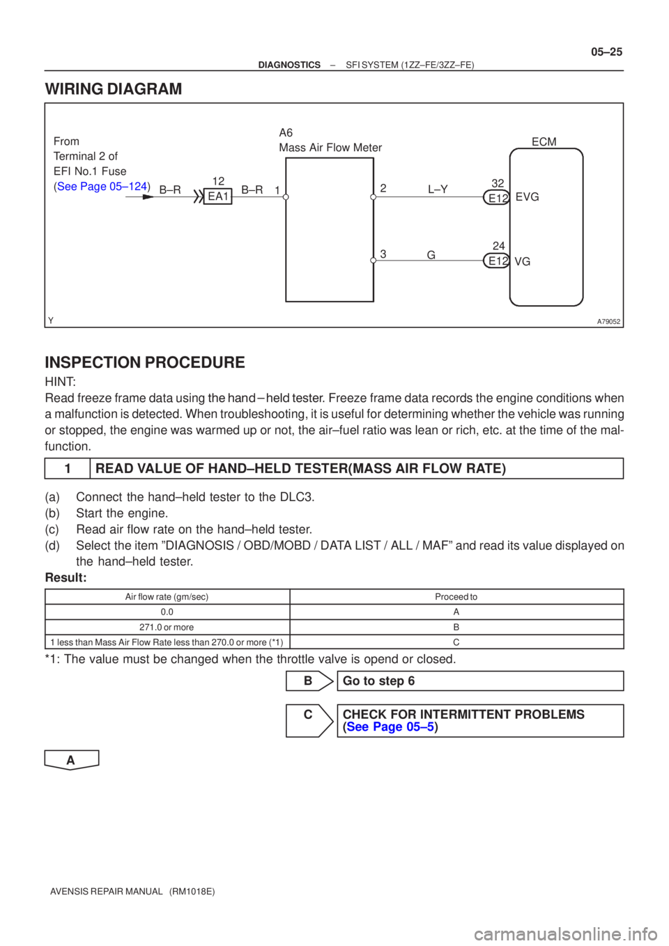
A79052
A6
Mass Air Flow MeterECM
1
3 EVG
VG
L±Y
G
2
B±R 12
EA1 32
E12
24
E12
B±R
From
Terminal 2 of
EFI No.1 Fuse
(See Page 05±124)
±
DIAGNOSTICS SFI SYSTEM(1ZZ±FE/3ZZ±FE)
05±25
AVENSIS REPAIR MANUAL (RM1018E)
WIRING DIAGRAM
INSPECTION PROCEDURE
HINT:
Read freeze frame data using \f���� ����\b�\f��\f�
� Freeze frame data records the engine conditions when
a malfunction is detected. When troubleshooting, it is useful for determi\
ning whether the vehicle was running
or stopped, the engine was warmed up or not, the air±fuel ratio was lea\
n or rich, etc. at the time of the mal-
function.
1READ VALUE OF HAND±HELD TESTER(MASS AIR FLOW RATE)
(a)Connect the hand±held tester to the DLC3.
(b)Start the engine.
(c)Read air flow rate on the hand±held tester.
(d)Select the item ºDIAGNOSIS / OBD/MOBD / DATA LIST / ALL / MAFº and read its value displayed on the hand±held tester.
Result:
Air flow rate (gm/sec)Proceed to
0.0A
271.0 or moreB
1 less than Mass Air Flow Rate less than 270.0 or more (*1)C
*1: The value must be changed when the throttle valve is opend or closed.
BGo to step 6
CCHECK FOR INTERMITTENT PROBLEMS(See Page 05±5)
A
Page 185 of 5135

0505L±04
05±22
±
DIAGNOSTICS SFI SYSTEM(1ZZ±FE/3ZZ±FE)
AVENSIS REPAIR MANUAL (RM1018E)
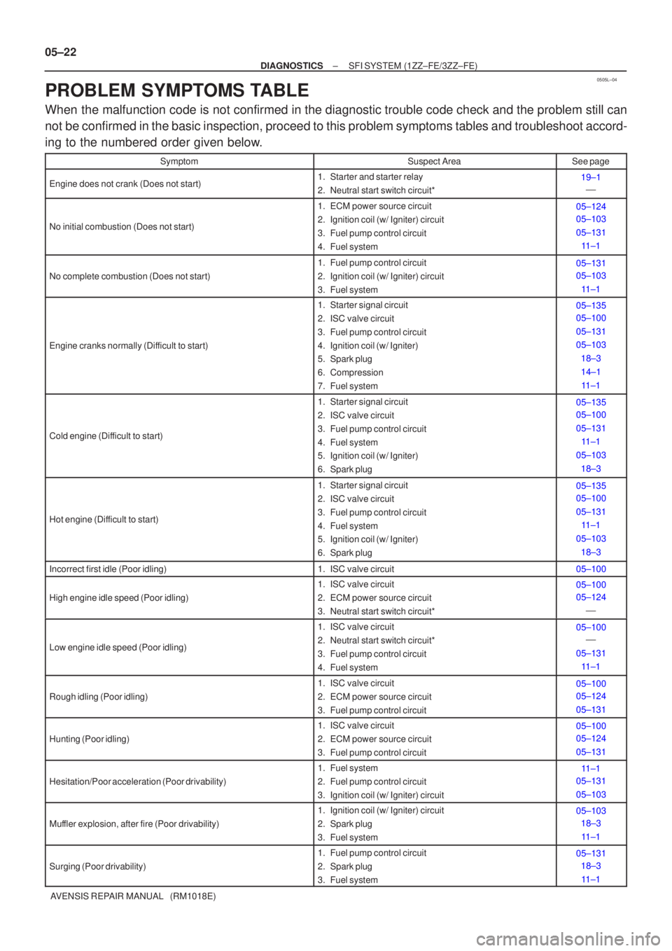
PROBLEM SYMPTOMS TABLE
When the malfunction code is not confirmed in the diagnostic trouble code check and the problem still can\
not be confirmed in the basic inspection, proceed to this problem symptoms \
tables and troubleshoot accord-
ing to the numbered order given below.
SymptomSuspect AreaSee page
Engine does not crank (Does not start)1. Starter and starter relay
2. Neutral start switch circuit*19±1 �
No initial combustion (Does not start)
1. ECM power source circuit
2. Ignition coil (w/ Igniter) circuit
3. Fuel pump control circuit
4. Fuel system05±124
05±103
05±131
11±1
No complete combustion (Does not start)
1. Fuel pump control circuit
2. Ignition coil (w/ Igniter) circuit
3. Fuel system05±131
05±103
11±1
Engine cranks normally (Difficult to start)
1. Starter signal circuit
2. ISC valve circuit
3. Fuel pump control circuit
4. Ignition coil (w/ Igniter)
5. Spark plug
6. Compression
7. Fuel system05±135
05±100
05±131
05±10318±3
14±111±1
Cold engine (Difficult to start)
1. Starter signal circuit
2. ISC valve circuit
3. Fuel pump control circuit
4. Fuel system
5. Ignition coil (w/ Igniter)
6. Spark plug05±135
05±100
05±131 11±1
05±103 18±3
Hot engine (Difficult to start)
1. Starter signal circuit
2. ISC valve circuit
3. Fuel pump control circuit
4. Fuel system
5. Ignition coil (w/ Igniter)
6. Spark plug05±135
05±100
05±131 11±1
05±103 18±3
Incorrect first idle (Poor idling)1. ISC valve circuit05±100
High engine idle speed (Poor idling)
1. ISC valve circuit
2. ECM power source circuit
3. Neutral start switch circuit*05±100
05±124 �
Low engine idle speed (Poor idling)
1. ISC valve circuit
2. Neutral start switch circuit*
3. Fuel pump control circuit
4. Fuel system05±100�
05±131 11±1
Rough idling (Poor idling)
1. ISC valve circuit
2. ECM power source circuit
3. Fuel pump control circuit05±100
05±124
05±131
Hunting (Poor idling)
1. ISC valve circuit
2. ECM power source circuit
3. Fuel pump control circuit05±100
05±124
05±131
Hesitation/Poor acceleration (Poor drivability)
1. Fuel system
2. Fuel pump control circuit
3. Ignition coil (w/ Igniter) circuit11±1
05±131
05±103
Muffler explosion, after fire (Poor drivability)
1. Ignition coil (w/ Igniter) circuit
2. Spark plug
3. Fuel system05±103 18±3
11±1
Surging (Poor drivability)
1. Fuel pump control circuit
2. Spark plug
3. Fuel system05±131 18±3
11±1
Page 186 of 5135
±
DIAGNOSTICS SFI SYSTEM (1ZZ±FE/3ZZ±FE)
05±23
AVENSIS REPAIR MANUAL (RM1018E)
Engine stall (Soon after starting)
1. Fuel pump control circuit
2. ISC valve circuit05±131
05±100
Engine stall (After accelerator pedal released)
1. Injector circuit
2. ISC valve circuit
3. ECM11±8
05±100
05±20
Engine stall (When shifting from N to D)1. Neutral start switch circuit
2. ISC valve circuit�
05±100
*: A/T only.
Page 189 of 5135
05B3M±03
A79104
Fuel Pump
Circuit Opening Relay
ECM
DLC3
Camshaft Position
Sensor
Engine Coolant
Temperature Sensor
Camshaft Timig OIL
Control Valve Assy
Crankshaft
Position Sensor
Knock Sensor
Mass Air Flow Meter Assy
Heated Oxygen Sensor
(Bank 1 Sensor 1)
Engine Room R/B No.1
Heated Oxygen Sensor
(Bank 1 Sensor 2)
Engine Room R/B No.4
Ignition Coil and Igniter
Injector
Power Steering Oil
Pressure Switch
Idle Speed Control
Valve Assy
Throttle Position Sensor
Vacuum Switching Valve
(for ISC)
VSV for EVAP
± DIAGNOSTICSSFI SYSTEM (1ZZ±FE/3ZZ±FE)
05±19
AVENSIS REPAIR MANUAL (RM1018E)
LOCATION