Page 1451 of 5135
�����������H42846
Airbag
Sensor
Assy
Center Knee Squib
DK± DK+Floor Wire
No.2 Instrument
Panel Wire
A
B C
D E F
����� �����H42847
Airbag
Sensor
Assy
Center Knee Squib
DK± DK+Floor Wire No.2
A
B C
D E F
05±1380
± DIAGNOSTICSSUPPLEMENTAL RESTRAINT SYSTEM
AVENSIS REPAIR MANUAL (RM1018E)
12 CHECK INSTRUMENT PANEL WIRE(TO GROUND)
(a) Disconnect the instrument panel wire connector from the
floor wire No.2.
(b) Measure the resistance between the body ground and
DK+ of the connector ºEº.
OK:
Resistance: 1 M� or Higher
NG REPAIR OR REPLACE INSTRUMENT PANEL
WIRE
OK
13 CHECK FLOOR WIRE NO.2(TO GROUND)
(a) Measure the resistance between the body ground and
DK+ of the connector ºCº.
OK:
Resistance: 1 M� or Higher
NG REPAIR OR REPLACE FLOOR WIRE NO.2
OK
14 USE SIMULATION METHOD TO CHECK
NG Go to step 1
OK
REPLACE ALL SRS COMPONENTS INCLUDING WIRE HARNESS
Page 1452 of 5135
�����������H42846
Airbag
Sensor
Assy
Center Knee Squib
DK± DK+Floor Wire
No.2 Instrument
Panel Wire
A
B C
D E F
����� �����H42847
Airbag
Sensor
Assy
Center Knee Squib
DK± DK+Floor Wire No.2
A
B C
D E F
± DIAGNOSTICSSUPPLEMENTAL RESTRAINT SYSTEM
05±1381
AVENSIS REPAIR MANUAL (RM1018E)
15 CHECK INSTRUMENT PANEL WIRE(OPEN)
(a) Disconnect the instrument panel wire connector from the
floor wire No.2.
(b) Measure the resistance between DK+ and DK± of the
connector ºEº.
OK:
Resistance: Below 1 �
NG REPAIR OR REPLACE INSTRUMENT PANEL
WIRE
OK
16 CHECK FLOOR WIRE NO.2(OPEN)
(a) Measure the resistance between DK+ and DK± of the
connector ºCº.
OK:
Resistance: Below 1 �
NG REPAIR OR REPLACE FLOOR WIRE NO.2
OK
USE SIMULATION METHOD TO CHECK
Page 1453 of 5135
�����\b�����H42846
Airbag
Sensor
Assy
Center
Knee Squib
DK±
DK+ Floor Wire
No.2
Instrument
Panel Wire
A
B
C
D
E
F
����� �����H42847
Airbag
Sensor
Assy
Center
Knee Squib
DK±
DK+ Floor Wire No.2
A
B
C
D
E
F
05±1382
±
DIAGNOSTICS SUPPLEMENTAL RESTRAINT SYSTEM
AVENSIS REPAIR MANUAL (RM1018E)
17CHECK INSTRUMENT PANEL WIRE(SHORT)
(a)Disconnect the instrument panel wire connector from the floor wire No.2.
(b)Release the activation prevention mechanism built in the connector ºDº (See page 05±1184).
(c) Measure the resistance between DK+ and DK± of the connector ºEº.
OK:
Resistance: 1 M � or Higher
NG REPAIR OR REPLACE INSTRUMENT PANEL WIRE
OK
18 CHECK FLOOR WIRE NO.2(SHORT)
(a) Release the activation prevention mechanism built in the connector ºBº.
(b) Measure the resistance between DK+ and DK± of the connector ºCº.
OK:
Resistance: 1 M � or Higher
NG REPAIR OR REPLACE FLOOR WIRE NO.2
OK
USE SIMULATION METHOD TO CHECK
Page 1454 of 5135

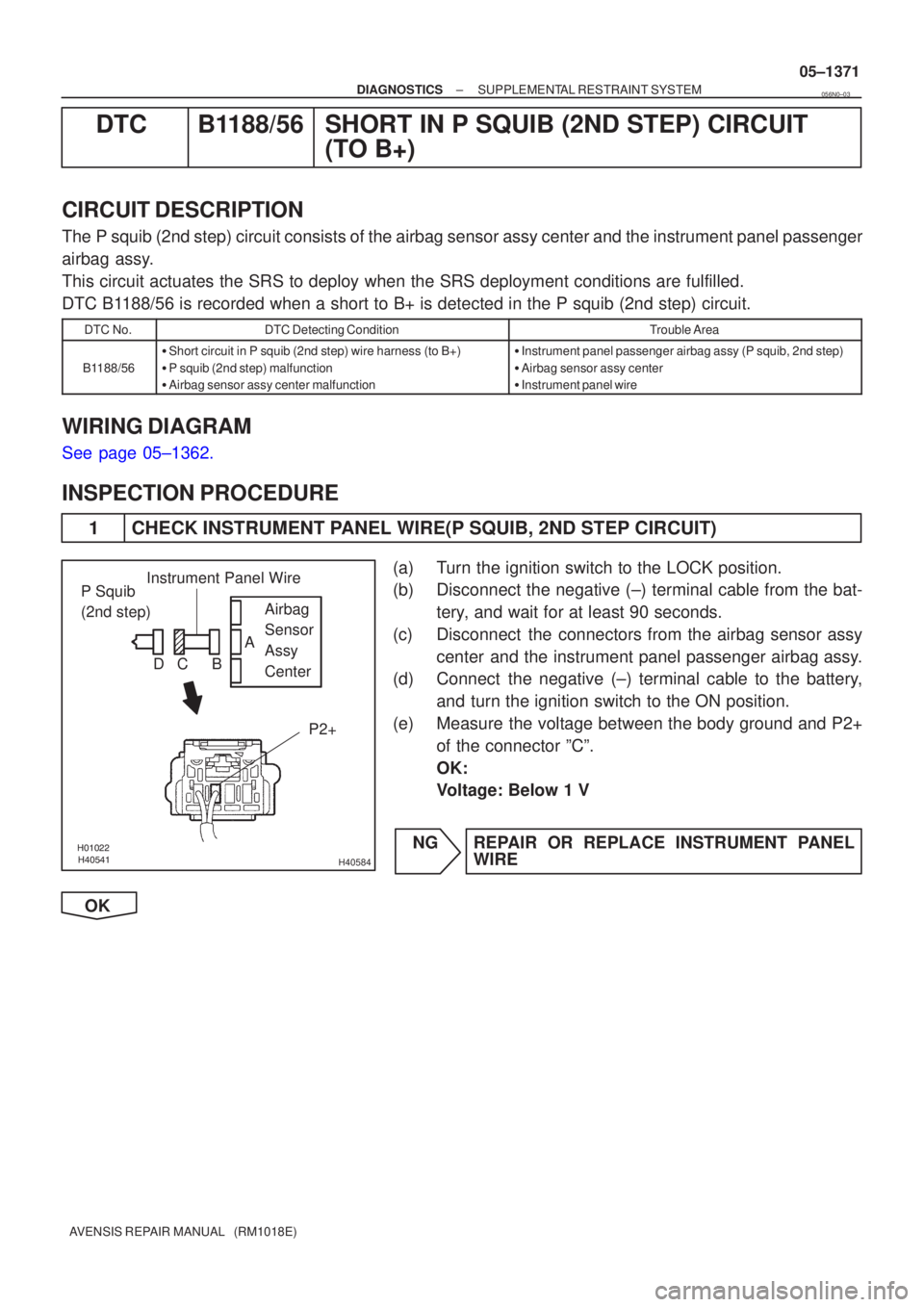
������������H40584
P Squib
(2nd step)Airbag
Sensor
Assy
Center
P2+Instrument Panel Wire
A
B
C
D
±
DIAGNOSTICS SUPPLEMENTAL RESTRAINT SYSTEM
05±1371
AVENSIS REPAIR MANUAL (RM1018E)
DTC B1188/56 SHORT IN P SQUIB (2ND STEP) CIRCUIT
(TO B+)
CIRCUIT DESCRIPTION
The P squib (2nd step) circuit consists of the airbag sensor assy center \
and the instrument panel passenger
airbag assy.
This circuit actuates the SRS to deploy when the SRS deployment conditio\
ns are fulfilled.
DTC B1188/56 is recorded when a short to B+ is detected in the P squib (2nd s\
tep) circuit.
DTC No.DTC Detecting ConditionTrouble Area
B1188/56
�Short circuit in P squib (2nd step) wire harness (to B+)
� P squib (2nd step) malfunction
� Airbag sensor assy center malfunction�Instrument panel passenger airbag assy (P squib, 2nd step)
� Airbag sensor assy center
� Instrument panel wire
WIRING DIAGRAM
See page 05±1362.
INSPECTION PROCEDURE
1 CHECK INSTRUMENT PANEL WIRE(P SQUIB, 2ND STEP CIRCUIT)
(a) Turn the ignition switch to the LOCK position.
(b) Disconnect the negative (±) terminal cable from the bat-
tery, and wait for at least 90 seconds.
(c) Disconnect the connectors from the airbag sensor assy center and the instrument panel passenger airbag assy.
(d) Connect the negative (±) terminal cable to the battery,
and turn the ignition switch to the ON position.
(e) Measure the voltage between the body ground and P2+ of the connector ºCº.
OK:
Voltage: Below 1 V
NG REPAIR OR REPLACE INSTRUMENT PANEL WIRE
OK
056N0±03
Page 1455 of 5135

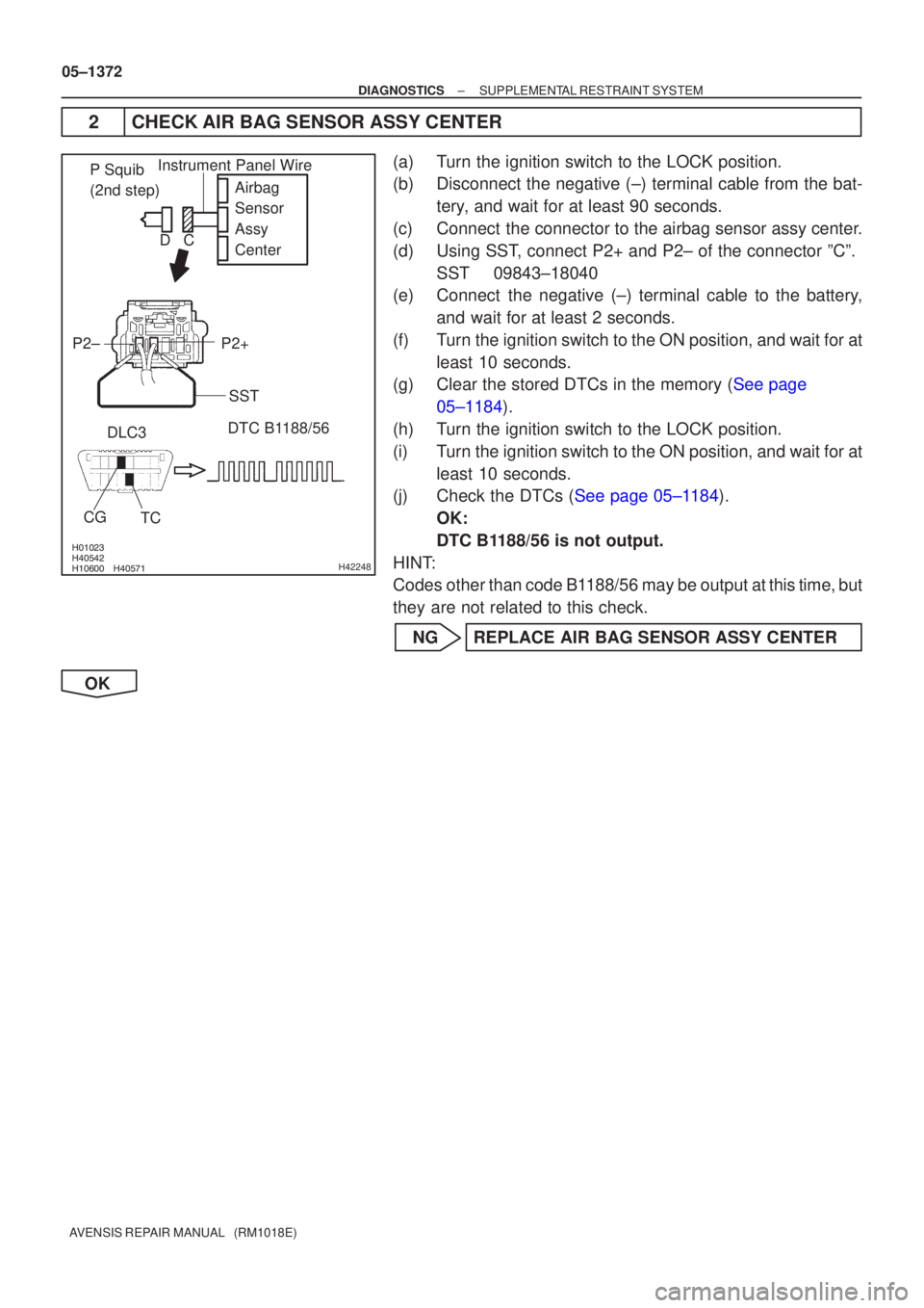
����� ����� ����� ���\b�H42248
Airbag
Sensor
Assy
Center
P2+
P2±
DTC B1188/56
DLC3
TC
CG
P Squib
(2nd step)Instrument Panel Wire
SST
C
D
05±1372
±
DIAGNOSTICS SUPPLEMENTAL RESTRAINT SYSTEM
AVENSIS REPAIR MANUAL (RM1018E)
2CHECK AIR BAG SENSOR ASSY CENTER
(a)Turn the ignition switch to the LOCK position.
(b)Disconnect the negative (±) terminal cable from the bat- tery, and wait for at least 90 seconds.
(c)Connect the connector to the airbag sensor assy center.
(d)Using SST, connect P2+ and P2± of the connector ºCº. SST09843±18040
(e)Connect the negative (±) terminal cable to the battery,
and wait for at least 2 seconds.
(f)Turn the ignition switch to the ON position, and wait for at least 10 seconds.
(g)Clear the stored DTCs in the memory (See page
05±1184).
(h) Turn the ignition switch to the LOCK position.
(i) Turn the ignition switch to the ON position, and wait for at least 10 seconds.
(j)Check the DTCs (See page 05±1184).
OK:
DTC B1188/56 is not output.
HINT:
Codes other than code B1188/56 may be output at this time, but
they are not related to this check.
NG REPLACE AIR BAG SENSOR ASSY CENTER
OK
Page 1456 of 5135

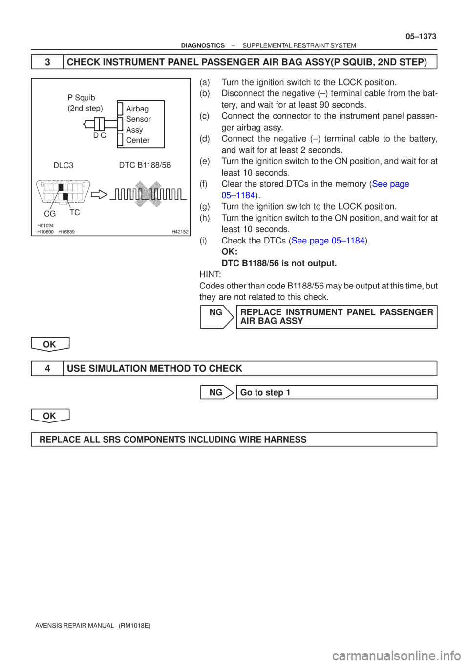
����� ����� ����\bH42152
DTC B1188/56
DLC3 Airbag
Sensor
Assy
Center
TC
CG
P Squib
(2nd step)
C
D
±
DIAGNOSTICS SUPPLEMENTAL RESTRAINT SYSTEM
05±1373
AVENSIS REPAIR MANUAL (RM1018E)
3CHECK INSTRUMENT PANEL PASSENGER AIR BAG ASSY(P SQUIB, 2ND STEP)
(a)Turn the ignition switch to the LOCK position.
(b)Disconnect the negative (±) terminal cable from the bat-
tery, and wait for at least 90 seconds.
(c)Connect the connector to the instrument panel passen- ger airbag assy.
(d)Connect the negative (±) terminal cable to the battery, and wait for at least 2 seconds.
(e)Turn the ignition switch to the ON position, and wait for at least 10 seconds.
(f)Clear the stored DTCs in the memory (See page 05±1184).
(g) Turn the ignition switch to the LOCK position.
(h) Turn the ignition switch to the ON position, and wait for at least 10 seconds.
(i)Check the DTCs (See page 05±1184). OK:
DTC B1188/56 is not output.
HINT:
Codes other than code B1188/56 may be output at this time, but
they are not related to this check.
NG REPLACE INSTRUMENT PANEL PASSENGER AIR BAG ASSY
OK
4 USE SIMULATION METHOD TO CHECK
NG Go to step 1
OK
REPLACE ALL SRS COMPONENTS INCLUDING WIRE HARNESS
Page 1527 of 5135

05C4G±01
I35933
C10 C11
05±1506
± DIAGNOSTICSCOMBINATION METER
AVENSIS REPAIR MANUAL (RM1018E)
TERMINALS OF ECU
COMBINATION METER ASSY
Terminal No.Wiring colorConditionSpecified condition
C11±1 ± Body ground
(TURN L ± Body ground)G±W ± Body
groundTurn signal LH indicator light OFF � ONBelow 1 V �
10 to 14 V
C11±2 ± Body ground
(BRAKE LVL SW ±
Body ground)R±W ± Body
groundBrake fluid level warning switch ONBelow 1 V
C11±3 ± Body ground
(TACHO ± Body ground)GR±R ± Body
groundIgnition switch OFF � ON, Engine idle speedPuls generation (*2)
C11±5 ± Body ground
(SIGNAL EARTH ±
Body ground)W±B ± Body
groundConstantContinuity
C11±6 ± Body ground
(EMPS ± Body ground)B±W ± Body
groundIgnition switch ON and EMPS Indicator OFF � ON10 to 14 V �
Below 1 V
C11±8 ± Body ground
(AIRBAG ± Body ground)B±Y ± Body
groundIgnition switch ON and AIRBAG Indicator OFF � ON10 to 14 V �
Below 1 V
C11±9 ± Body ground
(CHECK ENGINE ±
Body ground)
W ± Body groundEngine running and CHECK ENGINE indicator OFF9 to 14 V
C11±10 ± Body ground
(AUTO LEVELING ±
Body ground)LG ± Body
groundIgnition switch ON and AUTO LEVERING Indicator OFF � ON10 to 14 V �
Below 1 V
C11±11 ± Body ground
(OIL PRESS SW ±
Body ground)Y±B ± Body
groundEngine running�StoppedNo continuity �
Continuity
C11±12 ± Body ground
(BEAM+ ± Body ground)R±W (w/HID),
R (w/o HID) ±
Body ground
Headlight OFF�ONBelow 1 V �
10 to 14 V
C11±13 ± Body ground
(TURN R ± Body ground)G±Y ± Body
groundTurn signal RH indicator light OFF � ONBelow 1 V �
10 to 14 V
C11±14 ± Body ground
(ILL+ ± Body ground)G ± Body groundCombination switch OFF�ONBelow 1 V �
10 to 14 V
C11±15 ± Body ground
(SLIP ± Body ground)LG ± Body
groundIgnition switch ON and SLIP Indicator OFF � ON10 to 14 V �
Below 1 V
C11±16 ± Body ground
(VSC ± Body ground)W±R ± Body
groundIgnition switch ON and VSC Indicator OFF � ON10 to 14 V �
Below 1 V
Page 1535 of 5135
Terminal No.
Wire harness side
Turn Signal Flasher Relay
Skid Control ECU with Actuator Brake Fluid Level Warning Switch
Engine ECU
Oil Pressure Switch
DOME Fuse Headlight Beam Level Control ECU
Skid Control ECU with Actuator
Skid Control ECU with Actuator Turn Signal Flasher Relay Engine ECU ± Multi Display RAD No.1 Fuse
GND
EMPS ECU
TAIL Fuse
Skid Control ECU with Actuator Fuel Sensor Gauge
Skid Control ECU with Actuator
± GND
Rear Fog Light Relay Front Fog Light Relay Multi Display Fuse Filter Warning Switch (*1)
IGN Fuse Fuel Sender Gauge
Engine Oil Level Sensor Security ECU Ambient Temp. Sensor
4P OUT (Other Parts) H±HI RH Fuse/H±LP RH Fuse 1
2
3
4
5
6
7
8
9
10
11
12
13
14
15
16
17
18
19
201
2
3
4
5
6
7
8
9
10
11
12
13
14
15
16
17
18
C10
Airbag Sensor Assembly GND
GAUGE1 Fuse Skid Control ECU with Actuator
C11Engine ECU
Integration Relay
21
22
*1: 1CD±FTVAmbient Temp. Sensor
± DIAGNOSTICSCOMBINATION METER
05±1505
AVENSIS REPAIR MANUAL (RM1018E)