Page 2814 of 5135

54.INSTALL INSTRUMENT PANEL AIR BAG ASSY (See page 60±54)
55. INSTALL COLUMN")
F44800
Marks
F44801
Torx ScrewScrew Case
±
STEERING COLUMN STEERING COLUMN ASSY
50±19
AVENSIS REPAIR MANUAL (RM1018E)
54.INSTALL INSTRUMENT PANEL AIR BAG ASSY (See page 60±54)
55. INSTALL COLUMN HOLE COVER SILENCER SHEET
56. PLACE FRONT WHEELS FACING STRAIGHT AHEAD
57.INSTALL SPIRAL CABLE SUB±ASSY (See page 60±26)
58. CENTER SPIRAL CABLE
(a) Check that the front wheels are facing straight ahead.
(b) Turn the cable counterclockwise by hand until it becomesharder to turn.
(c) Then rotate the cable clockwise about 2.5 turns to align the marks.
HINT:
The cable will rotate about 2.5 turns to either left or right of the
center.
59. INSTALL STEERING WHEEL ASSY
(a) Align matchmarks on the steering wheel and main shaft assembly.
(b) Install the steering wheel set nut. Torque: 50 N´m (510 kgf´cm, 37 ft´lbf)
(c) Connect the connector.
60. INSTALL HORN BUTTON ASSY
NOTICE:
�Never use airbag parts from another vehicle. When
replacing parts, replace with new ones.
�Make sure the horn button assy is installed with the
specified torque.
�If the horn button assy has been dropped, or there are
cracks, dents or other defects in the case or connec-
tor, replace the horn button assy with a new one.
�When installing the horn button assy, take care that
the wirings do not interfere with other parts and that
they are not pinched between other parts.
(a) Connect the terminal.
(b) Connect the airbag connector.
(c) Install the steering horn button assy after confirming that the circumference groove of the torx screws is caught on
the screw case.
(d) Using a torx socket wrench, torque the 2 screws. Torque: 8.8 N´m (90 kgf´cm, 78 in.´lbf)
61. STEERING WHEEL CENTER POINT
62. CONNECT BATTERY NEGATIVE TERMINAL
63.INSPECT SRS WARNING LIGHT(See page 05±1184)
64. PERFORM CALIBRATION OF TORQUE SENSOR ZERO POINT (ELECTRIC POWER STEERING) (See page 05±1045)
Page 2815 of 5135

5006X−01
Steering
Column
Protector No.1
F44781
Horn Button Assy
Steering Wheel Assy
Spiral Cable Sub −Assy
Steering Column Cover
Headlamp Dimmer Switch AssySteering Column Assy
Steering
Sliding Yoke
Sub− Assy
Steering Intermediate
Shaft Assy No.2
Column Hole Cover Silencer Sheet
Steering Column Cover LWR
Windshield Wiper
Switch Assy
N
�m (kgf �cm, ft�lbf): Specified torque
OIL Pressure Power Steering:
Steering Intermediate
Shaft Assy No.2
Steering
Sliding Yoke
Sub−Assy
35 (360, 26)
Column Hole Cover
Silencer Sheet
LHD Steering Position Type:
LHD Steering Position
Type: w/ Instrument Cluster
Finish Panel Assy
Floor Shift
Parking Lock Cable
Assy (A/T Transaxle)
Instrument Panel
Hole Cover
5 (51, 44 in.�
�� � lbf)
18 (184, 13)
18 (184, 13)
Instrument Panel
Airbag Assy
18 (184, 13)
18 (184, 13)
18 (184, 13)
25 (255, 18)
50 (510, 37)
35 (360, 26)
35 (360, 26)
28 (286, 21)
35 (360, 26)
28 (286, 21)
25 (255, 18)
25 (255, 18)
−
STEERING COLUMN STEERING COLUMN ASSY
50−5
STEERING COLUMN ASSY
COMPONENTS
Page 2817 of 5135
F44779
Horn Button Assy
Steering Wheel Assy
Headlamp Dimmer Switcn Assy
Spiral Cable
Windshield Wiper Switch Steering Column Cover
Steering Column Assy
Steering
Intermediate
Shaft Assy
No.2
Steering Sliding
Yoke sub−assy
Column Hole Cover Silencer Sheet
N �m (kgf �cm, ft�lbf): Specified torque Steering Sliding
Yoke sub
−assy
Steering Intermediate
Shaft Assy No.2
LHD Steering Position Type:
Electric Power Steering:
35 (360, 26)
35 (360, 26)
35 (360, 26)
Column Hole Cover Silencer Sheet
Steering Column Cover
LW R
Floor Shift Parking Lock
Cable Assy (A/T Transaxle)
Instrument Panel Airbag Assy
18 (184, 13)
Steering
Column
Protector
No.1
Instrument
Panel
Hole Cover
18 (184, 13)
18 (184, 13)
5 (51, 44 in. �
�� � lbf)
25 (255, 18)
18 (184, 13)
18 (184, 13)
LHD Steering Position Type: w/ Instrument Cluster
Finish Panel Assy
50 (510, 37)
25 (255, 18)
Steering Column
Protector No.1
35 (360, 26)
M/T Transaxle:25 (255, 18)
−
STEERING COLUMN STEERING COLUMN ASSY
50−7
Page 2822 of 5135

STEERING SYSTEM
PRECAUTION
1. HANDLING PRECAUTIONS ON STEERING SYSTEM
(a) Be careful to replace the parts properly")
5000C±14
±
STEERING COLUMN STEERING SYSTEM
50±1
AVENSIS REPAIR MANUAL (RM1018E)
STEERING SYSTEM
PRECAUTION
1. HANDLING PRECAUTIONS ON STEERING SYSTEM
(a) Be careful to replace the parts properly because they could affect the performance of the steering sys-
tem and result in a driving hazard.
2. HANDLING PRECAUTIONS ON SRS AIRBAG SYSTEM
(a) The vehicle is equipped with SRS (Supplemental Restraint System) such as \
the driver airbag and front passenger airbag. Failure to carry out service operation in the correct sequence \
could cause the SRS
to unexpectedly deploy during servicing, possibly leading to a serious acc\
ident. Before servicing (in-
cluding removal or installation of parts, inspection or replacement), be sure \
to read the precautionary
notices in the supplemental restraint system (See page 60±1).
3. HANDLING PRECAUTIONS ON STEERING COLUMN
(a) Do not give an impact to the steering column assy, especially the motor and the torque sensor. If a great impact is given (dropping it to the floor, etc.), replace it with a new one.
(b) When removing the steering column assy, do not pull the harness.
(c) When having replaced the steering column assy and/or the ECU, calibrate the \
zero point of the steer- ing torque sensor.
(d) In the case of disconnecting a connector related to the power steering sys\
tem, turn the ignition switch ON, set the steering wheel in the straight±ahead position and turn th\
e ignition switch OFF before dis-
connecting the connector.
(e) In the case of connecting a connector related to the power steering system, make sure that the ignit\
ion switch is OFF at first. After connecting the connector, set the steering wheel assy in the straight±ahead
position, and then turn the ignition switch ON.
NOTICE:
Never turn on the ignition switch when the steering wheel assy is set in orde\
r than the straight±ahead
position.
(f) If the above operation is not done, the zero point of the steering torque \
sensor is shifted away from the proper position, making difference in the steering effort between right and left. If this happens, per-
form the zero point calibration of the steering torque sensor (See page 05±1042).
Page 2968 of 5135

REPLACEMENT
1.PRECAUTION (Se")
600JY±01
H42642
H42643
H42644
Hook
Airbag DoorHook
Front
±
SUPPLEMENTAL RESTRAINT SYSTEM INSTRUMENT PANEL PASSENGER AIR BAG ASSY
60±29
AVENSIS REPAIR MANUAL (RM1018E)
REPLACEMENT
1.PRECAUTION (See page 60±1)
2.DISCONNECT BATTERY NEGATIVE TERMINAL (See page 60±1)
3.REMOVE GLOVE COMPARTMENT DOOR ASSY (See page 71±11)
4. DISCONNECT PASSENGER AIRBAG CONNECTOR
(a) Remove the passenger airbag connector clip.
(b) Disconnect the passenger airbag connector.
5. REMOVE INSTRUMENT PANEL SUB±ASSY UPPER W/INSTR PNL PASS L/DOOR AIR BAG ASSY (See page 71±11)
6. REMOVE INSTRUMENT PANEL PASSENGER AIRBAG ASSY
(a) Remove the 2 screws.
(b) Release the rear side wall of the airbag door from the hook by slightly deflecting it and roll the instrument panel
passenger airbag assy forward.
(c) Release the front side wall of the airbag door from the oth-
er hook and remove the instrument panel passenger air-
bag assy.
7. INSTALL INSTRUMENT PANEL PASSENGER AIR BAG ASSY
8.INSPECT INSTRUMENT PANEL PASSENGER AIR BAG ASSY (See page 60±11)
9. INSTALL INSTRUMENT PANEL SUB±ASSY UPPER W/INSTR PNL PASS L/DOOR AIR BAG ASSY (See page 71±11)
10.INSPECT SRS WARNING LIGHT (See page 05±1184)
Page 2969 of 5135
600JX±01
H42775
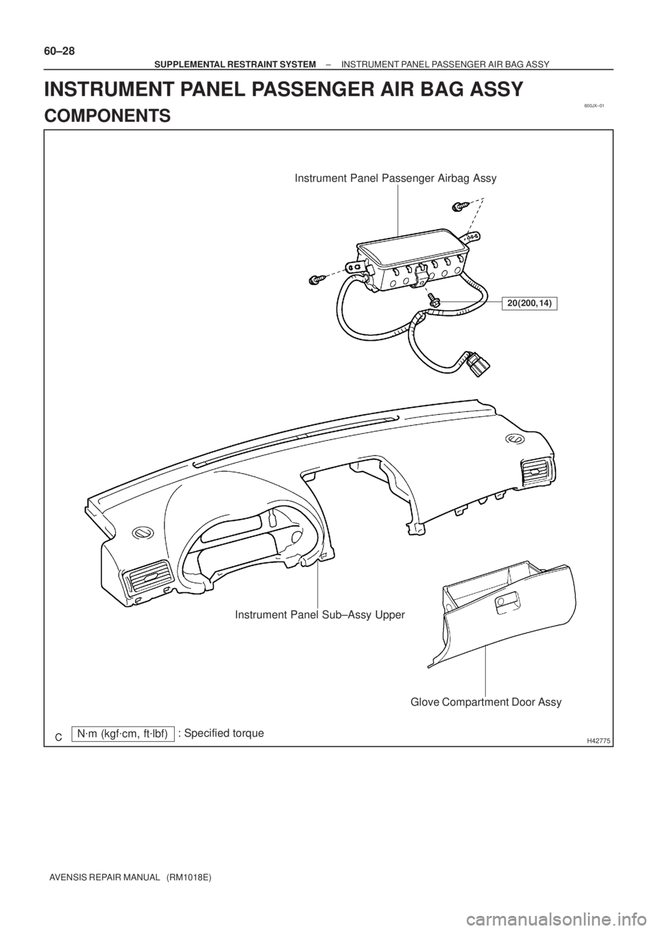
Instrument Panel Passenger Airbag Assy
Instrument Panel Sub±Assy Upper
Glove Compartment Door Assy
20 (200, 14)
N�m (kgf�cm, ft�lbf): Specified torque 60±28
± SUPPLEMENTAL RESTRAINT SYSTEMINSTRUMENT PANEL PASSENGER AIR BAG ASSY
AVENSIS REPAIR MANUAL (RM1018E)
INSTRUMENT PANEL PASSENGER AIR BAG ASSY
COMPONENTS
Page 2970 of 5135

SPIRAL CABLE SUB±ASSY
REPLACEMENT
HINT:
COMPONENTS: See page 60±16
1.PRE")
6009S±04
H42634
H42636 Claw
60±26
±
SUPPLEMENTAL RESTRAINT SYSTEM SPIRAL CABLE SUB±ASSY
AVENSIS REPAIR MANUAL (RM1018E)
SPIRAL CABLE SUB±ASSY
REPLACEMENT
HINT:
COMPONENTS: See page 60±16
1.PRECAUTION (See page 60±1)
2.DISCONNECT BATTERY NEGATIVE TERMINAL (See page 60±1)
3. PLACE FRONT WHEELS FACING STRAIGHT AHEAD
4.REMOVE HORN BUTTON ASSY (See page 60±17)
5.REMOVE STEERING WHEEL ASSY (See page 50±9) SST 09950±50013 (09951±05010, 09952±05010, 09953±05020, 09954±\
05021)
6.REMOVE INSTRUMENT PANEL HOLE COVER (See page 60±54)
7.REMOVE INSTRUMENT PANEL AIR BAG ASSY (See page 60±54)
8. REMOVE STEERING COLUMN COVER SUB±ASSYLOWER
(a) Remove the 3 screws and the steering column cover sub± assy lower.
9. REMOVE STEERING COLUMN COVER
W/INSTRUMENT CLUSTER FINISH PANEL ASSY
(a) Remove the steering column cover w/instrument cluster finish panel assy.
10. REMOVE SPIRAL CABLE SUB±ASSY
(a) Disconnect the airbag connector and the connector from the spiral cable sub±assy.
(b) Disengage the 3 claws and remove the spiral cable sub±
assy.
11.INSPECT SPIRAL CABLE SUB±ASSY (See page 60±11)
(a) If the following condition is identified, replace the spiral cable sub±\
assy with a new one. Condition:
Scratches or cracks on the connector
Cracks, dents or chips in the spiral cable sub±assy
12. PLACE FRONT WHEELS FACING STRAIGHT AHEAD
(a) Check that the front wheels are facing straight ahead.
Page 2971 of 5135

13. INSTALL SPIRAL CABLE SUB±ASSY
(a) Set the turn signal switch to the neutral pos")
H42637
H42638Marks
±
SUPPLEMENTAL RESTRAINT SYSTEM SPIRAL CABLE SUB±ASSY
60±27
AVENSIS REPAIR MANUAL (RM1018E)
13. INSTALL SPIRAL CABLE SUB±ASSY
(a) Set the turn signal switch to the neutral position.
NOTICE:
Make sure of the neutral position since the pin of the turn signal switc\
h may be snapped.
(b) Install the spiral cable sub±assy.
NOTICE:
When replacing the spiral cable sub±assy with a new one, remove the l\
ock pin before installing the
steering wheel assy.
(c) Connect the airbag connector and the connector.
(d) Install the steering column cover with the 3 screws.
14. ADJUST SPIRAL CABLE SUB±ASSY
(a) Check that the ignition switch is off.
(b) Check that the battery negative terminal is disconnected.
NOTICE:
Do not start the operation for 90 seconds after removing
the terminal.
(c) Turn the spiral cable sub±assy counterclockwise slowlyby hand until it feels firm.
(d) Then rotate the spiral cable sub±assy clockwise about 2.5 turns to align the marks.
HINT:
The spiral cable sub±assy will rotate about 2.5 turns to both left
and right of the center.
15.INSTALL STEERING COLUMN COVER SUB±ASSY LOWER (See page 50±9)
16.INSTALL INSTRUMENT PANEL AIR BAG ASSY (See page 60±54)
17.INSTALL STEERING WHEEL ASSY (See page 50±9)
18. INSPECT STEERING WHEEL CENTER POINT
19.INSTALL HORN BUTTON ASSY (See page 60±17)
20.INSPECT HORN BUTTON ASSY (See page 60±11)
21.INSPECT SRS WARNING LIGHT (See page 05±1184)