Page 2989 of 5135
H42671
Side Airbag
Sensor Assy RH
Airbag Front
RH Sensor
Airbag Sensor
Assy Center
Airbag Sensor
Front LH
Side Airbag
Sensor Assy LH
Airbag Sensor
Rear LH (*1)
Seat Position
Airbag Sensor
(*2)Horn Button Assy
(Squib) Instrument Panel
Passenger Airbag
Assy (Squib)Front Seat Outer
Belt Assy RH
(Squib)
Front Seat
Airbag Assy RH
(Squib)
Front Seat
Airbag Assy
LH (Squib)
Curtain Shield
Airbag Assy LH
(Squib) (*1) Airbag Sensor
Rear RH (*1)Curtain Shield
Airbag Assy RH
(Squib) (*1)
Front Seat Outer
Belt Assy LH
(Squib) Seat Position
Airbag Sensor
(*3)
Instrument Panel
Airbag Assy (Squib)
Spiral Cable
Sub±assy 7
15 8
16
513
614 3 11
412
19
210
23
24 2129
2230
1927
2028
17 25
1826
34 5
6
78
11
12 9
1025
26
27
28
29
30
*1: w/ Curtain Shield Airbag
*2: LHD
*3: RHD
*4: Knee Airbag
± SUPPLEMENTAL RESTRAINT SYSTEMSUPPLEMENTAL RESTRAINT SYSTEM
60±3
AVENSIS REPAIR MANUAL (RM1018E)
1. SRS CONNECTORS
Page 2991 of 5135

H41646
Disconnection
Detection
Pin
Airbag Sensor Assy Center
H01315
Terminal for Diagnosis
Disconnection Detection Pin �Half Connection�Complete Connection
Terminal for
Diagnosis
������H40180
Stopper
Locking PartSpring
Slider
Locking Arm
Rebounded by Slider
(Spring)Stopper
± SUPPLEMENTAL RESTRAINT SYSTEMSUPPLEMENTAL RESTRAINT SYSTEM
60±5
AVENSIS REPAIR MANUAL (RM1018E)
HINT:
The type of connector is shown in the diagram on the previous
page.
(3) Electrical connection check mechanism:
This mechanism electrically checks that the con-
nectors are connected correctly and completely.
The electrical connection check mechanism is de-
signed so that the disconnection detection pin con-
nects with the diagnosis terminals when the con-
nector housing lock is locked.
HINT:
The connectors shown in this illustration are connectors, º1º,
º2º, º3º and º4º in the step 1.
(4) Half connection prevention mechanism:
If the connector is not completely connected, the
connector is disconnected due to the spring opera-
tion to the extent that no continuity exists.
Page 2992 of 5135

(5) Co")
H40181
Claw
Groove
H42905
Fig.1
Fig.2
Power Source
Safing
Sensor
Squibs
Deceleration
Sensor 60±6
± SUPPLEMENTAL RESTRAINT SYSTEMSUPPLEMENTAL RESTRAINT SYSTEM
AVENSIS REPAIR MANUAL (RM1018E)
(5) Connector lock mechanism:
Locking the connector lock button connects the
connector securely.
(b) When the vehicle is involved in a frontal collision in the
hatched area (Fig. 1) and the shock is larger than the pre-
determined level, the SRS is activated automatically. The
safing sensor is designed to go on at a smaller decelera-
tion rate than the airbag sensor. As illustrated in the Fig.
2, ignition is caused when current flows to the squib,
which happens when the safing sensor and the decelera-
tion sensor go on simultaneously. When a deceleration
force acts on the sensors, 3 squibs in the driver airbag,
front passenger airbag and knee airbag ignite and gener-
ate gas. The gas discharging into the driver airbag, front
passenger airbag and knee airbag rapidly increases the
pressure inside the bags, breaking the horn button assy
and instrument panel. The inflation of the bag then ends,
and the bags deflate as the gas is discharged through dis-
charge holes at the bag's rear or side.
Page 2994 of 5135
H43007
(a)Black PartMark
(b)
Black Part
H43259
Black Part
60±8
± SUPPLEMENTAL RESTRAINT SYSTEMSUPPLEMENTAL RESTRAINT SYSTEM
AVENSIS REPAIR MANUAL (RM1018E)
4. DISCONNECTION OF CONNECTORS FOR INSTRUMENT PANEL AIRBAG ASSY
HINT:
Tape up the screwdriver tip before use.
(a) Release the black part of the connector using a screwdriver.
(b) Insert a screwdriver tip between the connector and the base, and then lever up connector.
5. DISCONNECTION OF CONNECTORS FOR INSTRUMENT PANEL AIRBAG ASSY
(a) Connect the connector.
(b) Push down securely on the yellow part of the connector.
Page 2995 of 5135
H01584
SliderSlider
Disconnection is completed
H01585
Slider
Slider
± SUPPLEMENTAL RESTRAINT SYSTEMSUPPLEMENTAL RESTRAINT SYSTEM
60±9
AVENSIS REPAIR MANUAL (RM1018E)
6. DISCONNECTION OF CONNECTOR FRONT SEAT AIRBAG ASSY
(a) Place a finger on the slider.
(b) Slide the slider to release lock.
(c) Disconnect the connector.
7. CONNECTION OF CONNECTOR FOR FRONT SEAT AIRBAG ASSY
(a) Align the lock part of the male connector and the slider of the female connector in the same direction
as shown in the illustration, connect them without rubbing together.
(b) Be sure to insert the connectors until they are locked. After connecting them, pull them slightly to check
that they are locked. (When locking, make sure that the slider returns to its original position and a click
sound can be heard.)
HINT:
When connecting them, the slider slides. Be sure not to touch the slider while connecting, as it may result
in an insecure fit.
Page 2996 of 5135

H02763
Outer
H02764
Connector lock is released
Disconnection is completed
H02768
Outer
Outer
Connection is completed 60±10
± SUPPLEMENTAL RESTRAINT SYSTEMSUPPLEMENTAL RESTRAINT SYSTEM
AVENSIS REPAIR MANUAL (RM1018E)
8. DISCONNECTION OF AIRBAG FRONT SENSOR, SIDE
AIRBAG SENSOR AND AIRBAG SENSOR REAR CON-
NECTOR
(a) While holding both outer flank sides of the outer, slide the
outer to the direction shown by the arrow.
(b) When the connector lock is released, the connectors are
disconnected.
HINT:
Be sure to hold both outer flank sides. If the top and bottom
sides are held, it will obstruct disconnection.
9. CONNECTION OF CONNECTORS FOR AIRBAG FRONT SENSOR, SIDE AIRBAG SENSOR AND
AIRBAG SENSOR REAR
(a) Align the male connector (on the side of sensor) and female connector in the same direction as shown
in the illustration and connect them without rubbing together.
(b) Be sure to insert the connectors until they are locked. After connecting them, pull them slightly to check
that they are locked. (When locking, make sure that the outer returns to its original position and a click
sound can be heard.)
HINT:
When connecting them, the outer slides. Be sure not to hold the outer while connecting, as it may result in
an insecure fit.
Page 3009 of 5135
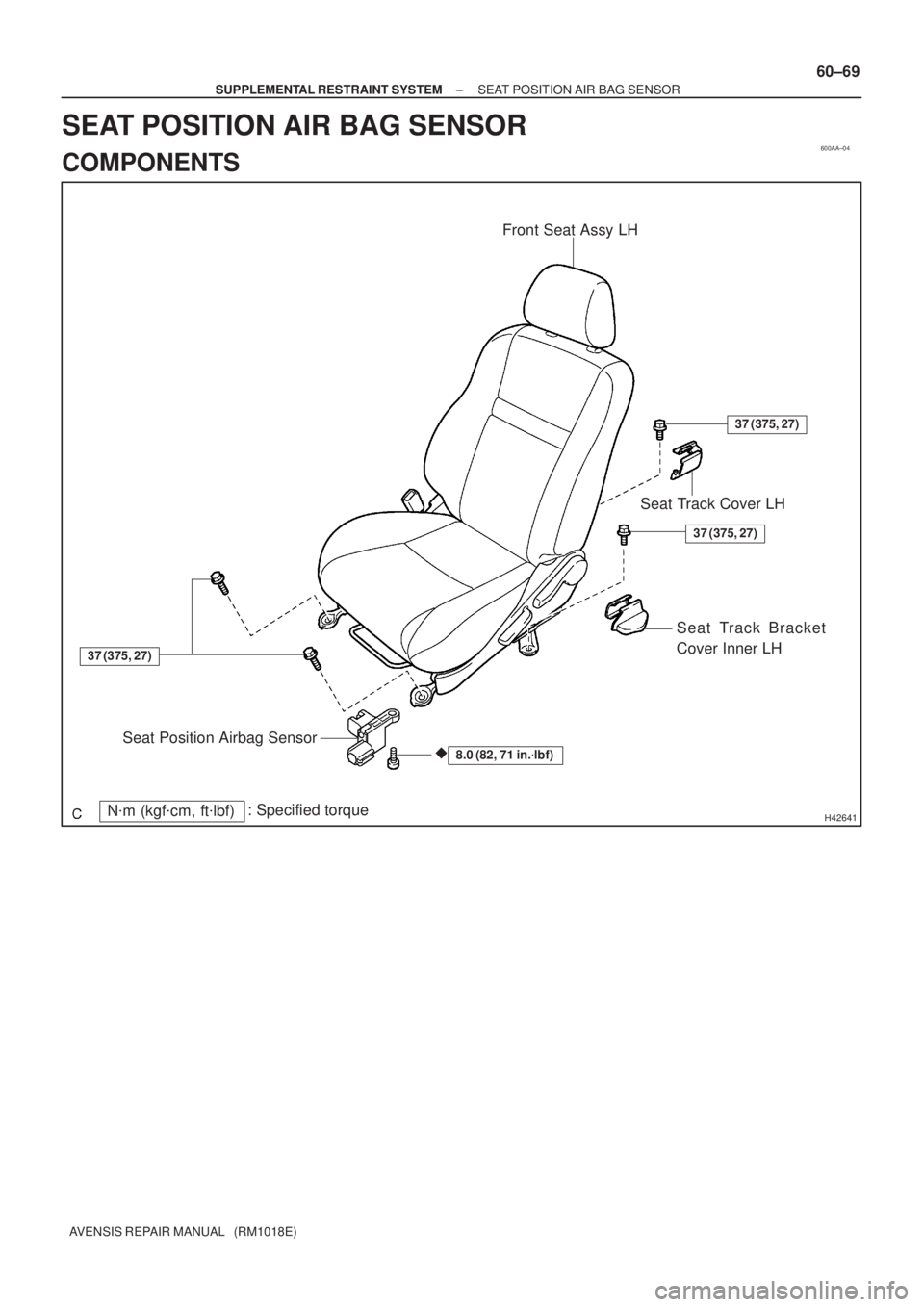
600AA±04
H42641N�m (kgf�cm, ft�lbf): Specified torqueFront Seat Assy LH
8.0 (82, 71 in.�lbf)
Seat Track Cover LH
Seat Track Bracket
Cover Inner LH
Seat Position Airbag Sensor
37 (375, 27)
37 (375, 27)
37 (375, 27)
�
± SUPPLEMENTAL RESTRAINT SYSTEMSEAT POSITION AIR BAG SENSOR
60±69
AVENSIS REPAIR MANUAL (RM1018E)
SEAT POSITION AIR BAG SENSOR
COMPONENTS
Page 3010 of 5135

REPLACEMENT
HINT:
Replacement procedure of the RH side is the same as that for the LH")
600K8±01
H42769
60±68
±
SUPPLEMENTAL RESTRAINT SYSTEM AIR BAG SENSOR REAR LH
AVENSIS REPAIR MANUAL (RM1018E)
REPLACEMENT
HINT:
Replacement procedure of the RH side is the same as that for the LH side.
1.PRECAUTION (See page 60±1)
2.DISCONNECT BATTERY NEGATIVE TERMINAL (See page 60±1)
3.REMOVE REAR DOOR SCUFF PLATE LH (See page 76±36)
4.REMOVE REAR SEAT CUSHION ASSEMBLY (SEDAN MODELS) (See page 76±36)
5.REMOVE REAR SIDE SEAT BACK ASSY LH (See page 76±36) 6. REMOVE AIR BAG SENSOR REAR LH
(a) Disconnect the connector of the airbag sensor rear LH.
(b) Remove the 2 bolts and the airbag sensor rear LH.
7.INSTALL AIR BAG SENSOR REAR LH (See page 60±11)
(a) Check that the ignition switch is off.
(b) Check that the battery negative (±) terminal is disconnected.
NOTICE:
Do not start the operation for 90 seconds after removing the terminal.
(c) Install the airbag sensor rear LH with the 2 bolts. Torque: 8.0 N �m (82 kgf �cm, 70 ft �lbf)
NOTICE:
�If the airbag sensor rear LH has been dropped, or there are any cracks, \
dents or other defects
in the case, bracket or connector, replace the airbag sensor rear LH with a new one.
�When installing the airbag sensor rear LH, take care that the SRS wiring does not interfere \
with
other parts and is not pinched between other parts.
(d) Connect the connector of the airbag sensor rear LH.
(e) Check that no play is identified.
8.INSPECT SRS WARNING LIGHT (See page 05±1184)

Seat Position
Airbag Sensor
(*2)Hor")
Black PartMark
(b)
Black Part
H43259
Black Part
60±8
± SUPPLEMENTAL RESTRAINT SYSTEMSUPPLEMENTAL RESTRAINT SYSTEM
AVENSIS REPAIR MANUAL (RM1018E)
4. DISCONNECTION OF CONNECTORS FOR INSTR")

6. DISCONNECTION OF CONNECTOR")