Page 1565 of 5135
I36641
14
C10 1
IC1
P±B MPX2
P±B 22
DCTY KSW
13
DB8
DA
B
J10B
J10 J/C
R
R14
IC2R
1 D9 Door Courtesy SWY1 2U1
Unlock Warning SW
W±B
(*7) W±B
(*5)
IL IO MPX1 11
P 10
IC1 29
A13 20
A15
3 24
A16 MPX±
PBLT A/C Control Assembly
F19 Front Passenger's
Seat Belt Warning Light
B10 Front Seat Inner Belt Assy
(Occupant Detection Sensor)
*1: Except Automatic A/C
*2: Automatic A/C
*3: 1AZ±FSE
*4: 1AZ±FE, 1ZZ±FE, 3ZZ±FE
*5: 1CD±FTV
*6: Except 1AZ±FE
*7: Except (*5) B±PBEW
PBEWA13 (*2) (*1)
(*1) (*2)P
B9
Buckle SwitchAirbag Sensor AssemblyDriver Side J/B
12
IC114
DB2
DD
L±R L±R
G±Y
W±B 3
1BKL 9
4
19
A26
2
A26L±R
GSWA27
LBE+
LBE±
G±Y (*6)14
IM1
G±Y (*6)3
1
W±B (*6)
W±B
BU BVI14
Driver Side J/B (Body ECU)Combination Meter Assy LHD Models:
6
7L±R (*6) 05±1530
± DIAGNOSTICSCOMBINATION METER
AVENSIS REPAIR MANUAL (RM1018E)
WARNING BUZZER DOES NOT SOUND
WIRING DIAGRAM
05C4P±01
Page 1566 of 5135
I36642
14
C10 1
IC1
P±B MPX2
P±B 22
DCTY KSW
13
DB8
DA
B
J10B
J10 J/C
R
R14
IC2R
1 D9 Door Courtesy SWY1 2U1
Unlock Warning SW
W±B
(*7) W±B
(*5)
IL IO MPX1 11
P 10
IC1 29
A13 20
A15
3 24
A16 MPX±
PBLT A/C Control Assembly
F19 Front Passenger's
Seat Belt Warning Light
*1: Except Automatic A/C
*2: Automatic A/C
*3: 1AZ±FSE
*4: 1AZ±FE, 1ZZ±FE, 3ZZ±FE
*5: 1CD±FTV
*6: Except 1AZ±FE
*7: Except (*5) B±PBEW
PBEWA13 (*2) (*1)
(*1) (*2)P
B9
Buckle SwitchAirbag Sensor AssemblyDriver Side J/B
12
IC114
DB2
DD
L±R L±R
G±Y
W±B 3
1BKL 9
4
14
A28
3
A28L±R
DBEWA27
RBE+
RBE±
G±Y (*6)8
IC3
G±Y (*6)3
1
W±B (*6)
BSI14
Driver Side J/B (Body ECU)Combination Meter Assy RHD Models:
3
2L±R (*6)
W±B (*6)
W±B (*6)C
J31J/C
B
J30J22
J/C
CC B10 Front Seat Inner Belt Assy
(Occupant Detection Sensor)
± DIAGNOSTICSCOMBINATION METER
05±1531
AVENSIS REPAIR MANUAL (RM1018E)
Page 1575 of 5135
I35763
I14
Body ECU
B9
Front Seat Inner Belt AssyCombination Meter Assy
Airbag Sensor AssemblyDriver Side J/B
*1: LHD Models
*2: RHD Models14
C10 1
IC1
12
IC114
DB2
DD
L±R P±B
L±R
G±Y
W±B 3
1 MPX2
BKLP±B
9 22
4
A27
19
A26 14
A28
2 3LBE+
RBE+
LBE±
RBE±(*1)
(*2) A26 A28(*1)
(*2) L±R
GSW
(*1) (*2)
(*1) (*2)DBEW(*1)
(*2)
05±1522
± DIAGNOSTICSCOMBINATION METER
AVENSIS REPAIR MANUAL (RM1018E)
SEAT BELT WARNING LAMP FOR DRIVER'S SEAT DOES NOT
OPERATE
WIRING DIAGRAM
INSPECTION PROCEDURE
1 READ VALUE OF HAND±HELD TESTER
(a) Operate the hand±held tester according to the steps on the display and select ºDATA LISTº.
BGW(Body):
ItemMeasurement Item/
Range (Display)Normal ConditionDiagnostic Note
D SEAT BUCKL SWDriver seat belt buckle switch ON /
OFFON: Fasten the driver seat belt
OFF: Unfasten the driver seat belt±
OK CHECK AND REPLACE COMBINATION METER
ASSY
NG
05C4M±01
Page 1576 of 5135

I35973
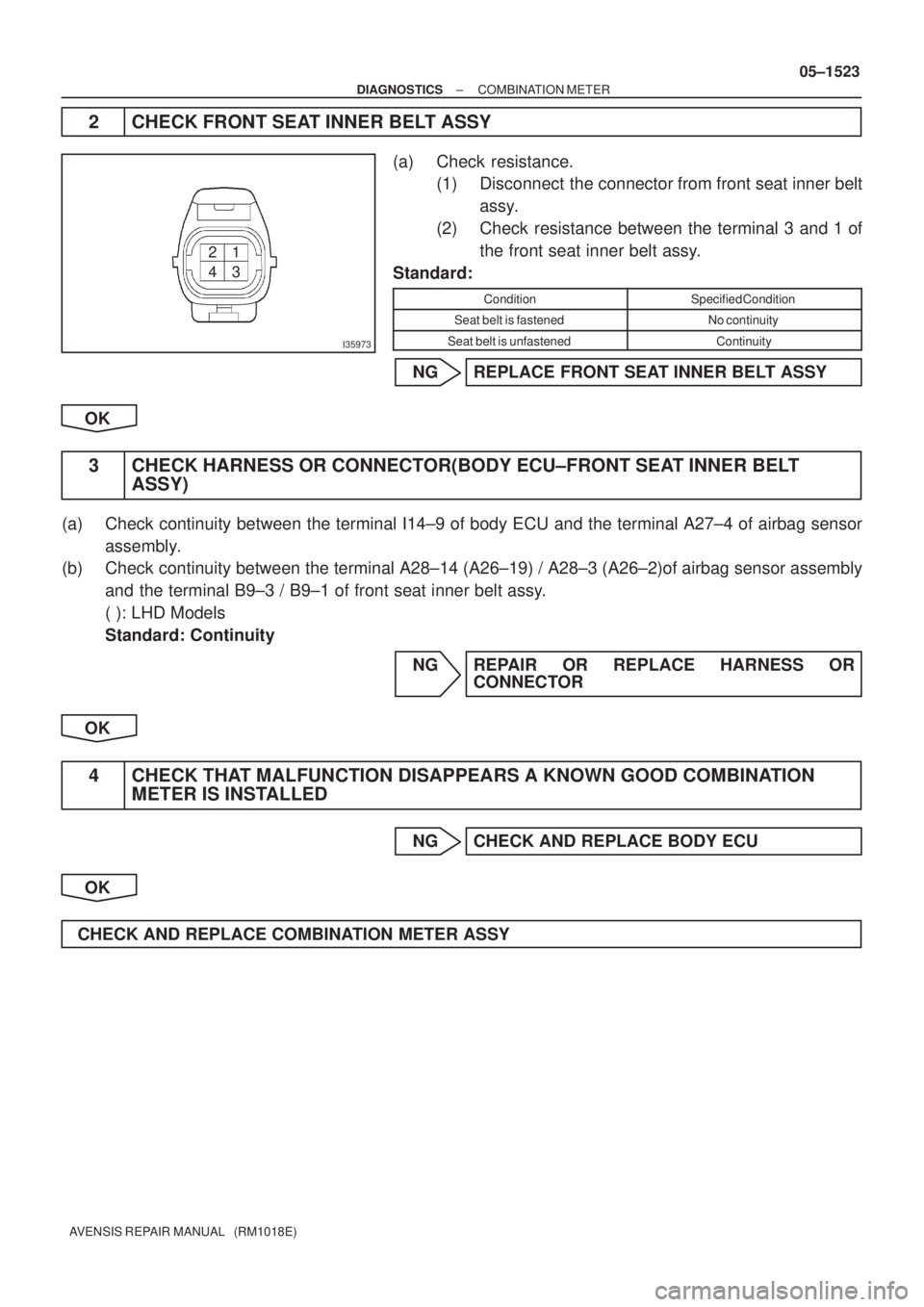
43 21
± DIAGNOSTICSCOMBINATION METER
05±1523
AVENSIS REPAIR MANUAL (RM1018E)
2 CHECK FRONT SEAT INNER BELT ASSY
(a) Check resistance.
(1) Disconnect the connector from front seat inner belt
assy.
(2) Check resistance between the terminal 3 and 1 of
the front seat inner belt assy.
Standard:
ConditionSpecified Condition
Seat belt is fastenedNo continuity
Seat belt is unfastenedContinuity
NG REPLACE FRONT SEAT INNER BELT ASSY
OK
3 CHECK HARNESS OR CONNECTOR(BODY ECU±FRONT SEAT INNER BELT
ASSY)
(a) Check continuity between the terminal I14±9 of body ECU and the terminal A27±4 of airbag sensor
assembly.
(b) Check continuity between the terminal A28±14 (A26±19) / A28±3 (A26±2)of airbag sensor assembly
and the terminal B9±3 / B9±1 of front seat inner belt assy.
( ): LHD Models
Standard: Continuity
NG REPAIR OR REPLACE HARNESS OR
CONNECTOR
OK
4 CHECK THAT MALFUNCTION DISAPPEARS A KNOWN GOOD COMBINATION
METER IS INSTALLED
NG CHECK AND REPLACE BODY ECU
OK
CHECK AND REPLACE COMBINATION METER ASSY
Page 2800 of 5135
5100F±06
±
POWER STEERING POWER STEERING SYSTEM
51±1
AVENSIS REPAIR MANUAL (RM1018E)
POWER STEERING SYSTEM
PRECAUTION
1. HANDLING PRECAUTIONS ON STEERING SYSTEM
(a) Care must be taken to replace parts properly because they could affect the performance of the steering
system and result in a driving hazard.
2. HANDLING PRECAUTIONS ON SRS AIRBAG SYSTEM
(a) The vehicle is equipped with SRS (Supplemental Restraint System) such as \
the driver airbag and front passenger airbag. Failure to carry out service operation in the correct sequence \
could cause the SRS
to unexpectedly deploy during servicing, possibly leading to a serious acc\
ident. Before servicing (in-
cluding removal or installation of parts, inspection or replacement), be sure \
to read the precautionary
notices in the supplemental restraint system (See page 60±1).
Page 2801 of 5135

5006Z±01
50±20
±
STEERING COLUMN POWER STEERING ECU ASSY
AVENSIS REPAIR MANUAL (RM1018E)
POWER STEERING ECU ASSY
REPLACEMENT
1.PRECAUTION (See page 60±1)
2.DISCONNECT BATTERY NEGATIVE TERMINAL (See page 60±1)
3.REMOVE INSTRUMENT CLUSTER FINISH PANEL GARNISH NO.1 (See page 71±11)
4.REMOVE INSTRUMENT CLUSTER FINISH PANEL GARNISH NO.2 (See page 71±11)
5.REMOVE INSTRUMENT PANEL REGISTER ASSY CTR (See page 71±11)
6.REMOVE STEERING COLUMN COVER LWR (See page 50±9)
7. REMOVE STEERING COLUMN COVER W/INSTRUMENT CLUSTER FINISH PANEL ASSY (See page 50±9)
8.REMOVE COMBINATION METER ASSY (See page 71±11)
9.REMOVE INSTRUMENT PANEL REGISTER ASSY NO.1 (See page 71±11)
10.REMOVE INSTRUMENT PANEL REGISTER ASSY NO.2(See page 71±11)
11.REMOVE GLOVE COMPARTMENT DOOR ASSY (See page 71±11)
12.REMOVE FRONT PILLAR GARNISH LH (See page 71±11)
13.REMOVE FRONT PILLAR GARNISH RH (See page 71±11)
14.DISCONNECT PASSENGER AIRBAG CONNECTOR(See page 71±11)
15. REMOVE INSTRUMENT PANEL SUB±ASSY UPPER W/INSTR PNL PASS L/DOOR AIR BAG
ASSY (See page 71±11)
16. REMOVE POWER STEERING ECU ASSY
NOTICE:
Thoroughly check the procedures for removing and instal-
ling the power steering ECU assy when replacing it. Do the
same for the removing and installing the steering column
assy.
(a) Mark the clamp position on the torque sensor wire har-ness in order to reinstall the wire harness as shown in the
illustration.
(b) Disconnect the torque sensor wire harness from the clamp.
NOTICE:
In case the clamp will be reused, pay attention so as not to
damage it.
(c) Disconnect the 4 connectors.
(d) LHD: (1) Remove the 2 bolts,screw and power steering ECUassy.
(e) RHD: (1) Remove the 2 bolts,2 screw and power steeringECU assy.
Page 2804 of 5135
5006Y±01
Screw Case
F44801
Torx Screw
F44804
Airbag Connector
Lock Part Pull Out
F44805
CorrectWrong
±
STEERING COLUMN STEERING COLUMN ASSY
50±9
AVENSIS REPAIR MANUAL (RM1018E)
OVERHAUL
1.PRECAUTION (See page 60±1)
2. INSPECT PLACE FRONT WHEELS FACING STRAIGHT AHEAD
3.DISCONNECT BATTERY NEGATIVE TERMINAL (See page 60±1)
4.REMOVE HORN BUTTON ASSY
NOTICE:
If the airbag connector is disconnected with the ignition
switch at ON, DTCs is recorded.
(a) Using a torx socket wrench, loosen the 2 torx screws untilthe groove along the screw circumference catches on the
screw case.
(b) Pull out the horn button assy from the steering wheel and disconnect the airbag connector.
(c) Disconnect the terminal.
NOTICE:
When removing the horn button assy, take care not to pull
the airbag wire harness.
CAUTION:
�When storing the horn button assy, keep the upper
surface of the horn button assy facing upward.
�Never disassemble the horn button assy.
Page 2805 of 5135

F44783
MatchmarksSST
F44784
50±10
±
STEERING COLUMN STEERING COLUMN ASSY
AVENSIS REPAIR MANUAL (RM1018E)
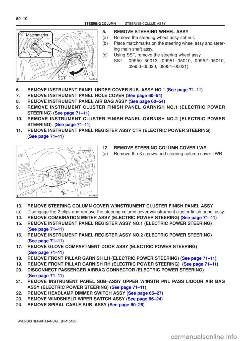
5. REMOVE STEERING WHEEL ASSY
(a) Remove the steering wheel assy set nut.
(b) Place matchmarks on the steering wheel assy and steer- ing main shaft assy.
(c) Using SST, remove the steering wheel assy. SST 09950±50013 (09951±05010, 09952±05010, 09953±05020, 09954±05021)
6.REMOVE INSTRUMENT PANEL UNDER COVER SUB±ASSY NO.1 (See page 71±11)
7.REMOVE INSTRUMENT PANEL HOLE COVER (See page 60±54)
8.REMOVE INSTRUMENT PANEL AIR BAG ASSY (See page 60±54)
9. REMOVE INSTRUMENT CLUSTER FINISH PANEL GARNISH NO.1 (ELECTRIC POWER STEERING) (See page 71±11)
10. REMOVE INSTRUMENT CLUSTER FINISH PANEL GARNISH NO.2 (ELECTRIC POWER
STEERING) (See page 71±11)
11. REMOVE INSTRUMENT PANEL REGISTER ASSY CTR (ELECTRIC POWER STEERING) (See page 71±11)
12. REMOVE STEERING COLUMN COVER LWR
(a) Remove the 3 screws and steering column cover LWR.
13. REMOVE STEERING COLUMN COVER W/INSTRUMENT CLUSTER FINISH PANEL ASSY
(a) Disengage the 2 clips and remove the steering column cover w/instrument cluster finish panel assy.
14.REMOVE COMBINATION METER ASSY (ELECTRIC POWER STEERING) (See page 71±11)
15. REMOVE INSTRUMENT PANEL REGISTER ASSY NO.1 (ELECTRIC POWER STEERING) (See page 71±11)
16. REMOVE INSTRUMENT PANEL REGISTER ASSY NO.2 (ELECTRIC POWER STEERING) (See page 71±11)
17. REMOVE GLOVE COMPARTMENT DOOR ASSY (ELECTRIC POWER STEERING)
(See page 71±11)
18.REMOVE FRONT PILLAR GARNISH LH (ELECTRIC POWER STEERING) (See page 71±11)
19.REMOVE FRONT PILLAR GARNISH RH (ELECTRIC POWER STEERING) (See page 71±11)
20. DISCONNECT PASSENGER AIRBAG CONNECTOR (ELECTRIC POWER STEERING) (See page 71±11)
21. REMOVE INSTRUMENT PANEL SUB±ASSY UPPER W/INSTR PNL PASS L/DOOR AIR BAG ASSY (ELECTRIC POWER STEERING) (See page 71±11)
22.REMOVE HEADLAMP DIMMER SWITCH ASSY (See page 65±27)
23.REMOVE WINDSHIELD WIPER SWITCH ASSY (See page 66±24)
24.REMOVE SPIRAL CABLE SUB±ASSY (See page 60±26)