Page 1143 of 5135
I35378
A25
Air Vent Mode Control Servo Motor A/C Control Assembly
M
FACE 5L±B
A15 AOF4
DEF 4LG±B
A15 AOD3
PT 3GR±R
A16 TPM19
VZ 2BR±W
A16 S5±314
GND 1G±W
A15 SG±315 05±1136
± DIAGNOSTICSAIR CONDITIONING SYSTEM
AVENSIS REPAIR MANUAL (RM1018E)
DTC 43 AIR OUTLET DAMPER CONTROL
SERVOMOTOR CIRCUIT
CIRCUIT DESCRIPTION
This circuit turns the servomotor and changes each mode damper position by the signals from the A/C ampli-
fier assy. When the AUTO switch is on, the A/C amplifier changes the mode automatically between ºFACEº,
ºBI±LEVELº, ºFOOTº and ºFOOT/DEFº according to the temperature setting.
DTC No.Detection ItemTrouble Area
43Air mode damper position sensor value does not change even
if A/C amplifier operated mode damper control servomotor.
�Mode damper servo sub±assy (mode damper control)
�Harness or connector between mode damper servo sub±
assy (mode damper control) and A/C amplifier assy
�A/C amplifier assy
WIRING DIAGRAM
05A87±02
Page 1146 of 5135

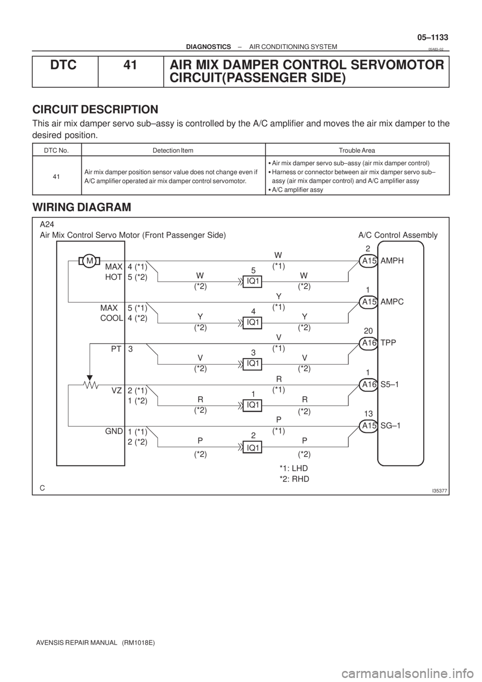
I35377
A24
Air Mix Control Servo Motor (Front Passenger Side) A/C Control Assembly
MA15 AMPH W
(*1)
W
(*2) W
(*2)5
IQ1 MAX 4 (*1)
HOT 5 (*2)
A15 AMPC Y
(*1)
Y
(*2) Y
(*2)4
IQ1 MAX 5 (*1)
COOL 4 (*2)2
1
A16 TPP V
(*1)
V
(*2) V
(*2)3
IQ1 PT20
3
A16 S5±1 R
(*1)
R
(*2) R
(*2)1
IQ1 VZ 2 (*1)
1 (*2)1
A15 SG±1 P
(*1)
P
(*2) P
(*2)2
IQ1 GND
1 (*1)
2 (*2)13
*1: LHD
*2: RHD
± DIAGNOSTICSAIR CONDITIONING SYSTEM
05±1133
AVENSIS REPAIR MANUAL (RM1018E)
DTC 41 AIR MIX DAMPER CONTROL SERVOMOTOR
CIRCUIT(PASSENGER SIDE)
CIRCUIT DESCRIPTION
This air mix damper servo sub±assy is controlled by the A/C amplifier and moves the air mix damper to the
desired position.
DTC No.Detection ItemTrouble Area
41Air mix damper position sensor value does not change even if
A/C amplifier operated air mix damper control servomotor.
�Air mix damper servo sub±assy (air mix damper control)
�Harness or connector between air mix damper servo sub±
assy (air mix damper control) and A/C amplifier assy
�A/C amplifier assy
WIRING DIAGRAM
05A83±02
Page 1149 of 5135
4(V)
1
0
100%
TPI terminal voltage
Damper opening angle
I35378
A23
Air Mix Control Servo Motor (Driver Side) A/C Control Assembly
M
MAX
HOT4P±L
A15 AMDH12
MAX
COOL5B
A15 AMDC11
PT 3GR
A16 TPD8
VZ 2Y±B
A16 S5±22
GND 1Y±R
A15 SG±214
± DIAGNOSTICSAIR CONDITIONING SYSTEM
05±1129
AVENSIS REPAIR MANUAL (RM1018E)
DTC 36 AIR MIX DAMPER POSITION SENSOR
CIRCUIT (DRIVER SIDE)
CIRCUIT DESCRIPTION
This sensor detects the position of the air mix damper and
sends the appropriate signals to the A/C amplifier. The position
sensor is built in the air mix damper servo sub±assy.
DTC No.Detection ItemTrouble Area
36Short to ground or power source circuit in air mix damper posi-
tion sensor circuit.
�Air mix damper servo sub±assy (Air mix damper position
sensor)
�Harness or connector between air mix damper servo sub±
assy (air mix damper position sensor) and A/C amplifier assy
�A/C amplifier assy
WIRING DIAGRAM
05A80±02
Page 1153 of 5135
TPM terminal voltage
(V)
4
1
0 100%
Damper opening angle
I35378
A25
Air Vent Mode Control Servo Motor A/C Control Assembly
M
FACE 5L±B
A15 AOF4
DEF 4LG±B
A15 AOD3
PT 3GR±R
A16 TPM19
VZ 2BR±W
A16 S5±314
GND 1G±W
A15 SG±315 05±1126
± DIAGNOSTICSAIR CONDITIONING SYSTEM
AVENSIS REPAIR MANUAL (RM1018E)
DTC 33 AIR OUTLET DAMPER POSITION SENSOR
CIRCUIT
CIRCUIT DESCRIPTION
This sensor detects the position of the mode damper and sends
the appropriate signals to the A/C amplifier. The position sensor
is built in the mode damper servo sub±assy.
DTC No.Detection ItemTrouble Area
33Short to ground or power source circuit in mode damper posi-
tion sensor circuit.
�Mode damper servo sub±assy (mode damper position sen-
sor)
�Harness or connector between mode damper servo sub±
assy (mode damper position sensor) and A/C amplifier assy
�A/C amplifier assy
WIRING DIAGRAM
05A7X±02
Page 1156 of 5135

4
1
0
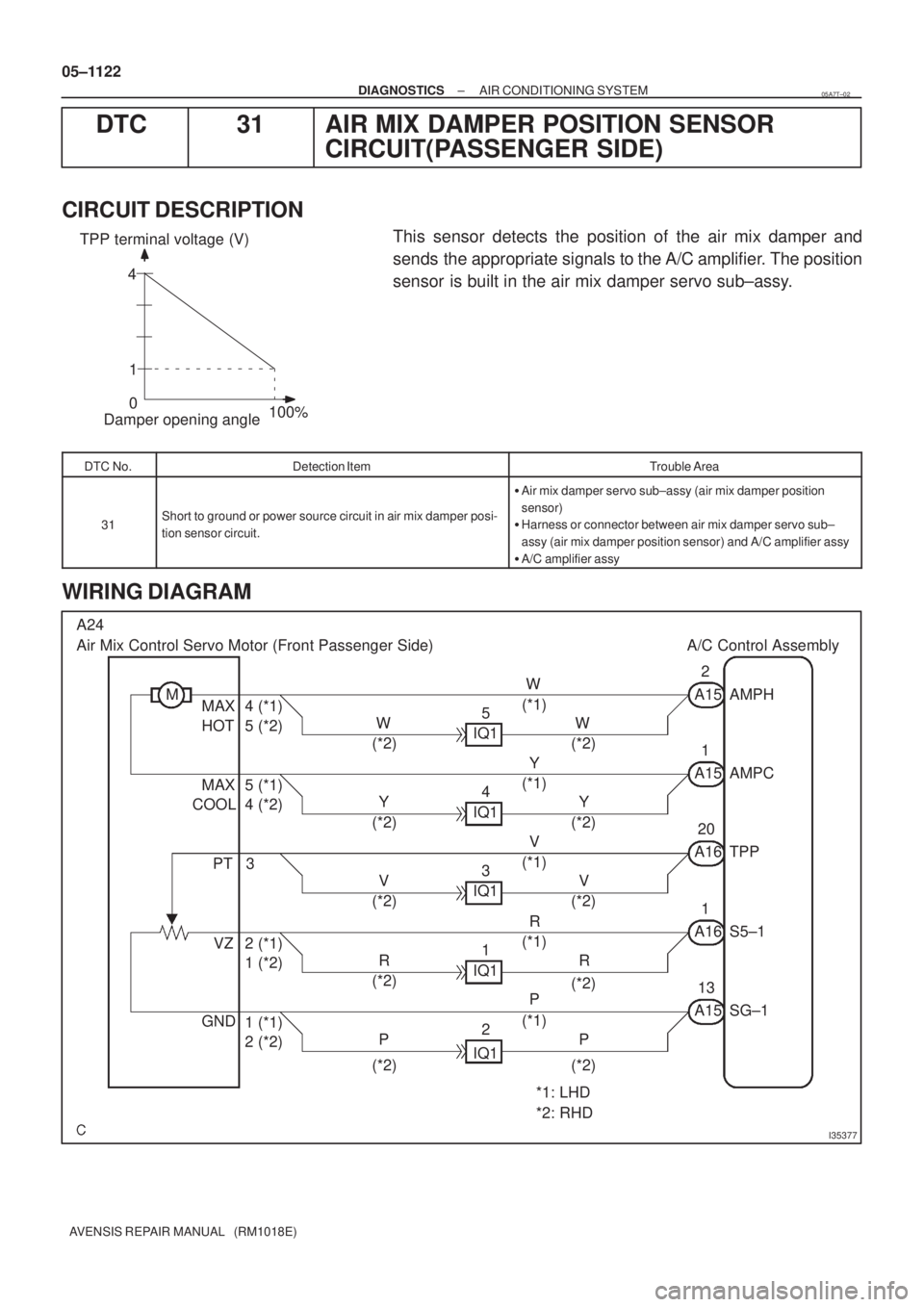
100%Damper opening angle TPP terminal voltage (V)
I35377
A24
Air Mix Control Servo Motor (Front Passenger Side) A/C Control Assembly
MA15 AMPH W
(*1)
W
(*2) W
(*2)5
IQ1 MAX 4 (*1)
HOT 5 (*2)
A15 AMPC Y
(*1)
Y
(*2) Y
(*2)4
IQ1 MAX 5 (*1)
COOL 4 (*2)2
1
A16 TPP V
(*1)
V
(*2) V
(*2)3
IQ1 PT20
3
A16 S5±1 R
(*1)
R
(*2) R
(*2)1
IQ1 VZ 2 (*1)
1 (*2)1
A15 SG±1 P
(*1)
P
(*2) P
(*2)2
IQ1 GND
1 (*1)
2 (*2)13
*1: LHD
*2: RHD 05±1122
± DIAGNOSTICSAIR CONDITIONING SYSTEM
AVENSIS REPAIR MANUAL (RM1018E)
DTC 31 AIR MIX DAMPER POSITION SENSOR
CIRCUIT(PASSENGER SIDE)
CIRCUIT DESCRIPTION
This sensor detects the position of the air mix damper and
sends the appropriate signals to the A/C amplifier. The position
sensor is built in the air mix damper servo sub±assy.
DTC No.Detection ItemTrouble Area
31Short to ground or power source circuit in air mix damper posi-
tion sensor circuit.
�Air mix damper servo sub±assy (air mix damper position
sensor)
�Harness or connector between air mix damper servo sub±
assy (air mix damper position sensor) and A/C amplifier assy
�A/C amplifier assy
WIRING DIAGRAM
05A7T±02
Page 1160 of 5135
Resistance of photodiode
Strength of solar radiationWeak Strong
High
Low
I35375
TSP A16 L21 A18
A/C Solar Sensor
2IF11A/C Control Assembly
L
TSD A16 LG9
3IF12
LG
S5±4 A16 O15
1IF13
O
± DIAGNOSTICSAIR CONDITIONING SYSTEM
05±1119
AVENSIS REPAIR MANUAL (RM1018E)
DTC 24 SOLAR SENSOR CIRCUIT (DRIVER SIDE)
CIRCUIT DESCRIPTION
A photo diode in the solar sensor detects solar radiation and
sends signals to the A/C amplifier.
DTC No.Detection ItemTrouble Area
Open or short in solar sensor circuit�Automatic light control sensor (solar sensor)
24
Open or short in solar sensor circuit.
(If the checking is being performed in a dark place, DTC 24g()
�Harness or connector between automatic light control sensor
(solar sensor) and A/C amplifier assy(gg ,
could be displayed.)(solar sensor) and A/C amplifier assy
�A/C amplifier assy
WIRING DIAGRAM
05C7N±01
Page 1163 of 5135
I35376
A3
A/C Pressure Sensor A/C Control Assembly
VC
3B±W
IE2 A16 S516 7
B±W
GND
1G±W
IE2 A16 SG18 8
G±W
VOUT
2L±W
IE2 A16 PRE7 17
L±W 05±1116
± DIAGNOSTICSAIR CONDITIONING SYSTEM
AVENSIS REPAIR MANUAL (RM1018E)
DTC 23 PRESSURE SWITCH CIRCUIT
CIRCUIT DESCRIPTION
The pressure sensor sends the appropriate signals to the A/C amplifier assy when the A/C refrigerant pres-
sure drops too low or rises too high. When the A/C amplifier receives these signals, it outputs signals though
the A/C amplifier to switch OFF the compressor relay and turns the magnetic clutch OFF.
DTC No.Detection ItemTrouble Area
23
�Open in pressure sensor circuit.
�Abnormal refrigerant pressure.
below 196 kPa (2.0 kgf/cm
2, 28 psi)
over 3,140 kPa (32.0 kgf/cm2, 455 psi)
�A/C tube assy (pressure sensor)
�Harness or connector between A/C tube assy (pressure sen-
sor) and A/C amplifier assy
�A/C amplifier assy
WIRING DIAGRAM
0564B±07
Page 1164 of 5135

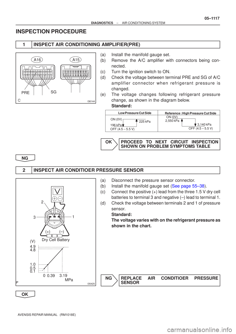
I36144
PRESG
A16A15
Low Pressure Cut Side
Reference : High Pressure Cut Side
ON (0V)
196 kPa
OFF (4.5 ± 5.5 V) 225 kPa
ON (0V)
2,550 kPa
3,140 kPa
OFF (4.5 ± 5.5 V)
I35425
Dry Cell Battery
MPa
3.19
0.1 0.5 1.0 4.8 4.9 (V) (+)(±) 1
2
3
0.39
0
±
DIAGNOSTICS AIR CONDITIONING SYSTEM
05±1117
AVENSIS REPAIR MANUAL (RM1018E)
INSPECTION PROCEDURE
1INSPECT AIR CONDITIONING AMPLIFIER(PRE)
(a)Install the manifold gauge set.
(b)Remove the A/C amplifier with connectors being con-
nected.
(c)Turn the ignition switch to ON.
(d)Check the voltage between terminal PRE and SG of A/C
amplifier connector when refrigerant pressure is
changed.
(e)The voltage changes following refrigerant pressure
change, as shown in the diagram below.
Standard:
OKPROCEED TO NEXT CIRCUIT INSPECTION SHOWN ON PROBLEM SYMPTOMS TABLE
NG
2INSPECT AIR CONDITIOER PRESSURE SENSOR
(a)Disconnect the pressure sensor connector.
(b)Install the manifold gauge set (See page 55±38).
(c) Connect the positive (+) lead from the three 1.5 V dry cell batteries to terminal 3 and negative (±) lead to terminal 1.
(d) Check the voltage between terminals 2 and 1 of pressure sensor.
Standard:
The voltage varies with on the refrigerant pressure as
shown in the chart.
NG REPLACE AIR CONDITIOER PRESSURE SENSOR
OK