Page 1072 of 5135
D26545
THO E2 BR
30
V E2 E1
ECT Solenoid
E13 O
THO OECM
28
E13
6
1
± DIAGNOSTICSELECTRONIC CONTROLLED AUTOMATIC
TRANSAXLE [ECT] (U341E)05±1003
AVENSIS REPAIR MANUAL (RM1018E)
DTC P0710 TRANSMISSION FLUID TEMPERATURE
SENSOR CIRCUIT MALFUNCTION
CIRCUIT DESCRIPTION
The ATF temperature sensor converts the fluid temperature into a resistance value which is input into the
ECM.
DTC No.DTC Detection ConditionTrouble Area
P0710
Either (a) or (b) is detected for 0.5 sec. or more:
(1 trip detection logic)
(c) Temp. sensor resistance is less than 79 �
(d) After engine has been operating for 15 min. or
more, resistance at temp. sensor is more than 156 k�
�Open or short in ATF temp. sensor circuit
�Transmission wire (ATF temperature sensor)
�ECM
WIRING DIAGRAM
0567Z±06
Page 1077 of 5135
F40038
Power Steering ECU Assy
Power Steering MotorM1
M2 1
2 05±1064
± DIAGNOSTICSELECTRONIC MOTOR POWER STEERING SYSTEM
AVENSIS REPAIR MANUAL (RM1018E)
DTC C1523/23 Motor Circuit Malfunction
DTC C1524/24 Motor Circuit Malfunction
CIRCUIT DESCRIPTION
DTC No.DTC Detecting ConditionTrouble Area
C1523/23Short circuit of motor terminal or abnormal voltage or current in�Steering column assy
C1524/24
Short circuit of motor terminal or abnormal voltage or current in
motor circuit.
Steering column assy
�Power steering ECU assy
WIRING DIAGRAM
050WR±04
Page 1081 of 5135
F44868
Power Steering ECU Assy Torque Sensor
TRQV
TRQ1
TRQ2
TRQG 6
5
7
8
± DIAGNOSTICSELECTRONIC MOTOR POWER STEERING SYSTEM
05±1059
AVENSIS REPAIR MANUAL (RM1018E)
DTC C1511/11 Torque Sensor Circuit Malfunction
DTC C1512/12 Torque Sensor Circuit Malfunction
DTC C1513/13 Torque Sensor Circuit Malfunction
DTC C1514/14 Torque Sensor Power Source Circuit
Malfunction
DTC C1517/17 Torque Sensor Hold Malfunction
CIRCUIT DESCRIPTION
The torque sensor converts the power input in the steering wheel into electric signals, and sends them to
the ECU.
DTC No.DTC Detecting ConditionTrouble Area
C1511/11
C1512/12Torque sensor circuit malfunction
C1513/13
q�Steering column assy
�Power steering ECU assy
C1514/14Torque sensor power source circuit malfunction
�Power steering ECU assy
C1517/17Torque sensor hold malfunction
WIRING DIAGRAM
05C5H±01
Page 1101 of 5135
D30688
ECM
MPX2
MPX1 29
23 E10 11
I14
22 SNOWI14
Integration Relay
8
Driver Side J/B14
DA B E8
ECT Pattern Select SW
*1: RHD
*2: LHD 4 1 W±B
CH
CF
CA 8
11
6
W±B
IPI14 E10 MPX1
MPX2
*1
*2
05±1040± DIAGNOSTICSELECTRONIC CONTROLLED AUTOMATIC
TRANSAXLE [ECT] (U341E)
AVENSIS REPAIR MANUAL (RM1018E)
PATTERN SELECT SWITCH CIRCUIT
CIRCUIT DESCRIPTION
When SNOW mode is selected with the pattern select switch, the ECM controls the solenoid valves and the
transmission starts from 2nd gear.
In D range, the transmission automatically shifts up through 3rd to O/D as usual.
WIRING DIAGRAM
05C8Q±01
Page 1104 of 5135
D30750
ECM
SPT1
SFTD
SFTU L
B
R8
30
23 E10
7
1
2
5J17
J/C
W±B(*1)
(*2) A
A S
SFTD
SFTU
E IG 3 R±WT7
Transmission Control SW
Center J/B
Driver Side J/B
I13
Ignition SW
Engine Room J/B No.4
FL MAIN
Battery
*1: LHD
*2 RHDIJIK IPJ15
J/C A AM1 IG1R±W
W±B B±G
G±Y7
1
CA
7
DB
9
DA
1
DH AM1 GAUGE1 IG1 Relay
5
13
2 DN
31
1
4D1
4B ALT
21E10
E10
W±B
W±B
CG
R±W 1
5
DH
G±R
G±Y
W±B
B±G R±W
B±G 05±1036
± DIAGNOSTICSELECTRONIC CONTROLLED AUTOMATIC
TRANSAXLE [ECT] (U341E)
AVENSIS REPAIR MANUAL (RM1018E)
WIRING DIAGRAM
Page 1108 of 5135
G25416
ECM
KD *
112
E10 K2
Kick Down SW
IP6
CA
12 CJ
W±BCenter J/B
6
IG1 IG112
W WW±B W±B
*1: LHD
± DIAGNOSTICSELECTRONIC CONTROLLED AUTOMATIC
TRANSAXLE [ECT] (U341E)05±1033
AVENSIS REPAIR MANUAL (RM1018E)
KICK DOWN SWITCH CIRCUIT
CIRCUIT DESCRIPTION
The kick±down switch is turned ON when the accelerator pedal is depressed to the full throttle and sends
signals to ECM.
When the kick±down switch is turned ON, the ECM controls gear shifting according to the programmed shift
diagrams.
If a short circuit develops in the kick±down switch, the ECM disregards the kick±down signals and controls
shifting at the normal shift points.
WIRING DIAGRAM
05C8O±01
Page 1112 of 5135

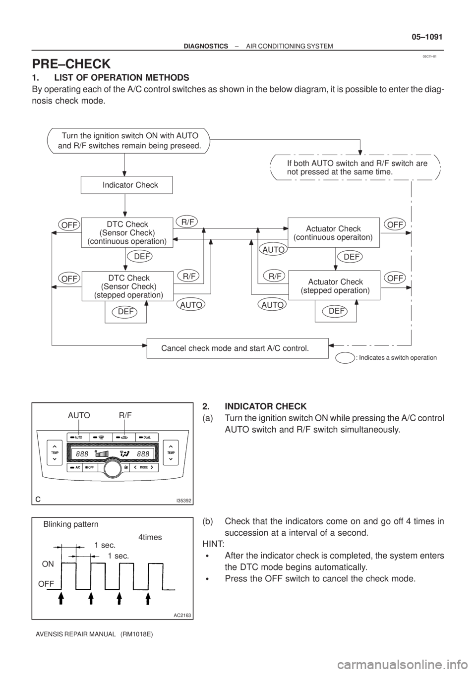
05C7I±01
Turn the ignition switch ON with AUTO
and R/F switches remain being preseed.
Indicator Check
DTC Check
(Sensor Check)
(continuous operation)
DTC Check
(Sensor Check)
(stepped operation)
Cancel check mode and start A/C control.
OFF
OFF
DEF
Actuator Check
(continuous operaiton)OFF
Actuator Check
(stepped operation)OFF
If both AUTO switch and R/F switch are
not pressed at the same time.
R/F
R/FR/F
AUTO
: Indicates a switch operation
AUTOAUTO
DEF
DEF
DEF
I35392
AUTO R/F
AC2163
Blinking pattern
ON
OFF1 sec.4times
1 sec.
± DIAGNOSTICSAIR CONDITIONING SYSTEM
05±1091
AVENSIS REPAIR MANUAL (RM1018E)
PRE±CHECK
1. LIST OF OPERATION METHODS
By operating each of the A/C control switches as shown in the below diagram, it is possible to enter the diag-
nosis check mode.
2. INDICATOR CHECK
(a) Turn the ignition switch ON while pressing the A/C control
AUTO switch and R/F switch simultaneously.
(b) Check that the indicators come on and go off 4 times in
succession at a interval of a second.
HINT:
�After the indicator check is completed, the system enters
the DTC mode begins automatically.
�Press the OFF switch to cancel the check mode.
Page 1118 of 5135
F44863
D5
DLC3Power Steering
ECU Assy
J/C
TS
CG12
4J8D (*1)
J16
J/CA J20D (*2)
J20D
(*2)J9B
(*1)W (*1) W
Center J/B
CB3
CA6E1511
IO IP *1: LHD
*2 RHD TS
W (*2)
W±B (*2)
W±B (*1)
A W±B (*2)
W±B (*1) 05±1086
± DIAGNOSTICSELECTRONIC MOTOR POWER STEERING SYSTEM
AVENSIS REPAIR MANUAL (RM1018E)
TS TERMINAL CIRCUIT
CIRCUIT DESCRIPTION
After making short circuit between terminal Ts and CG of DLC3 with turning the ignition switch OFF, the mode
will change from the normal mode to test mode when the ignition switch is turned ON. After the ignition switch
is turned ON, there will be DTC output from Tc terminal of DLC3.
WIRING DIAGRAM
050XA±04