Page 1252 of 5135
������
������ ������H40988
Side Squib LHDTC B0115/47
DLC3
TC
CG Airbag
Sensor
Assy
Center
C
D
05±1240
±
DIAGNOSTICS SUPPLEMENTAL RESTRAINT SYSTEM
AVENSIS REPAIR MANUAL (RM1018E)
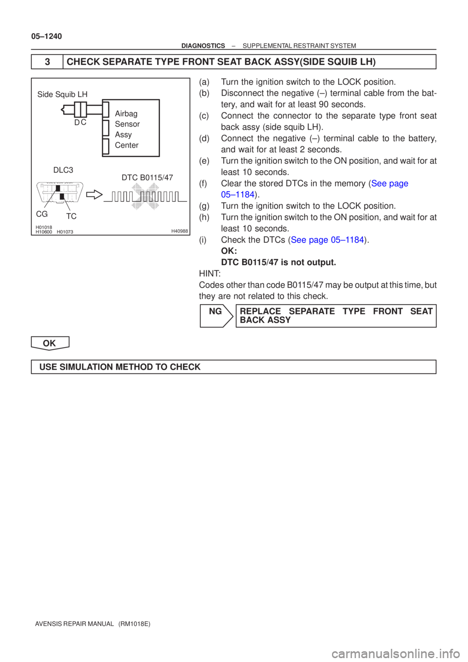
3 CHECK SEPARATE TYPE FRONT SEAT BACK ASSY(SIDE SQUIB LH)
(a) Turn the ignition switch to the LOCK position.
(b) Disconnect the negative (±) terminal cable from the bat- tery, and wait for at least 90 seconds.
(c) Connect the connector to the separate type front seat back assy (side squib LH).
(d) Connect the negative (±) terminal cable to the battery, and wait for at least 2 seconds.
(e) Turn the ignition switch to the ON position, and wait for at least 10 seconds.
(f)Clear the stored DTCs in the memory (See page 05±1184).
(g) Turn the ignition switch to the LOCK position.
(h) Turn the ignition switch to the ON position, and wait for at least 10 seconds.
(i)Check the DTCs (See page 05±1184). OK:
DTC B0115/47 is not output.
HINT:
Codes other than code B0115/47 may be output at this time, but
they are not related to this check.
NG REPLACE SEPARATE TYPE FRONT SEAT BACK ASSY
OK
USE SIMULATION METHOD TO CHECK
Page 1254 of 5135
\b�����
\b����� \b�����\b�����H42852
Side Squib RHAirbag
Sensor
Assy
Center
SFR±
SFR+
DLC3
CG TC DTC B0113/42
Floor Wire No.2
Service Wire
C
D
05±1236
±
DIAGNOSTICS SUPPLEMENTAL RESTRAINT SYSTEM
AVENSIS REPAIR MANUAL (RM1018E)
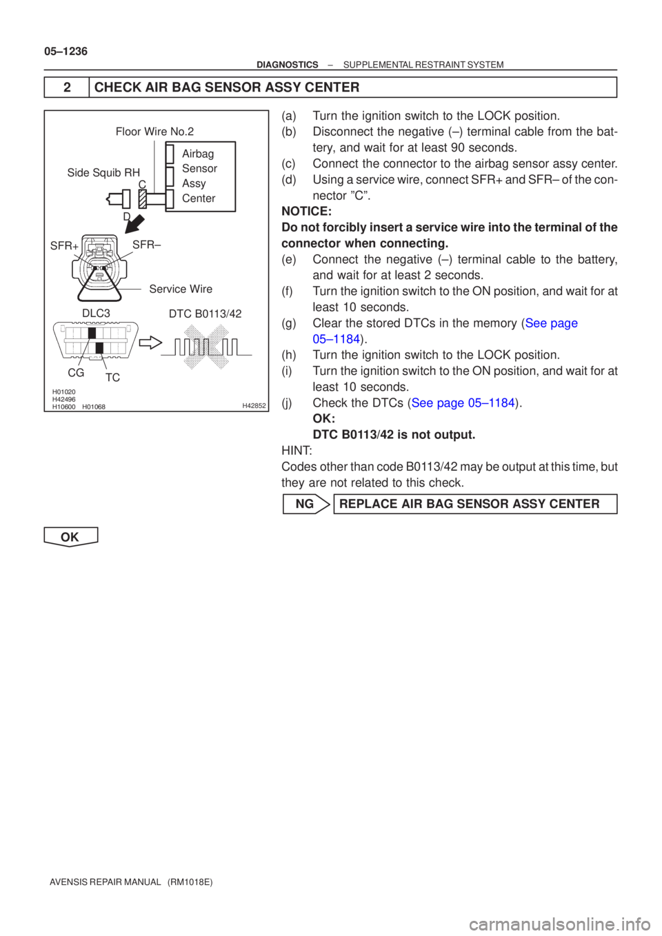
2 CHECK AIR BAG SENSOR ASSY CENTER
(a) Turn the ignition switch to the LOCK position.
(b) Disconnect the negative (±) terminal cable from the bat- tery, and wait for at least 90 seconds.
(c) Connect the connector to the airbag sensor assy center.
(d) Using a service wire, connect SFR+ and SFR± of the con- nector ºCº.
NOTICE:
Do not forcibly insert a service wire into the terminal of the
connector when connecting.
(e) Connect the negative (±) terminal cable to the battery, and wait for at least 2 seconds.
(f) Turn the ignition switch to the ON position, and wait for at least 10 seconds.
(g)Clear the stored DTCs in the memory (See page 05±1184).
(h) Turn the ignition switch to the LOCK position.
(i) Turn the ignition switch to the ON position, and wait for at
least 10 seconds.
(j)Check the DTCs (See page 05±1184). OK:
DTC B0113/42 is not output.
HINT:
Codes other than code B0113/42 may be output at this time, but
they are not related to this check.
NG REPLACE AIR BAG SENSOR ASSY CENTER
OK
Page 1255 of 5135
������
������ ������H40985
Side Squib RHCG DTC B0113/42
DLC3
TC Airbag
Sensor
Assy
Center
C
D
±
DIAGNOSTICS SUPPLEMENTAL RESTRAINT SYSTEM
05±1237
AVENSIS REPAIR MANUAL (RM1018E)
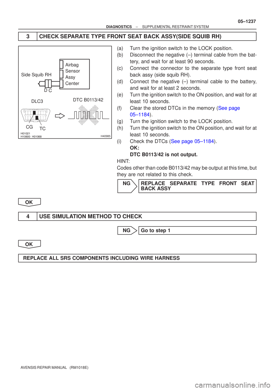
3 CHECK SEPARATE TYPE FRONT SEAT BACK ASSY(SIDE SQUIB RH)
(a) Turn the ignition switch to the LOCK position.
(b) Disconnect the negative (±) terminal cable from the bat-
tery, and wait for at least 90 seconds.
(c) Connect the connector to the separate type front seat back assy (side squib RH).
(d) Connect the negative (±) terminal cable to the battery, and wait for at least 2 seconds.
(e) Turn the ignition switch to the ON position, and wait for at least 10 seconds.
(f)Clear the stored DTCs in the memory (See page 05±1184).
(g) Turn the ignition switch to the LOCK position.
(h) Turn the ignition switch to the ON position, and wait for at least 10 seconds.
(i)Check the DTCs (See page 05±1184). OK:
DTC B0113/42 is not output.
HINT:
Codes other than code B0113/42 may be output at this time, but
they are not related to this check.
NG REPLACE SEPARATE TYPE FRONT SEAT BACK ASSY
OK
4 USE SIMULATION METHOD TO CHECK
NG Go to step 1
OK
REPLACE ALL SRS COMPONENTS INCLUDING WIRE HARNESS
Page 1257 of 5135
\b�����
\b�����\b�����\b�����H42851
Side Squib RHAirbag
Sensor
Assy
Center
SFR±
SFR+
CG
TC
DLC3
DTC B0112/41
Floor Wire No.2
Service Wire
C
D
±
DIAGNOSTICS SUPPLEMENTAL RESTRAINT SYSTEM
05±1233
AVENSIS REPAIR MANUAL (RM1018E)
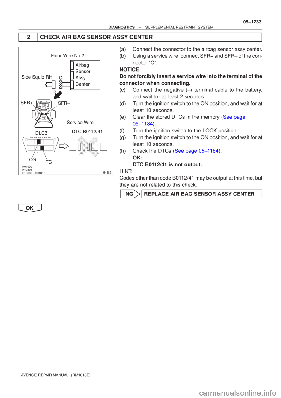
2CHECK AIR BAG SENSOR ASSY CENTER
(a)Connect the connector to the airbag sensor assy center.
(b)Using a service wire, connect SFR+ and SFR± of the con-
nector ºCº.
NOTICE:
Do not forcibly insert a service wire into the terminal of the
connector when connecting.
(c)Connect the negative (±) terminal cable to the battery, and wait for at least 2 seconds.
(d)Turn the ignition switch to the ON position, and wait for at least 10 seconds.
(e)Clear the stored DTCs in the memory (See page
05±1184).
(f) Turn the ignition switch to the LOCK position.
(g) Turn the ignition switch to the ON position, and wait for at least 10 seconds.
(h)Check the DTCs (See page 05±1184).
OK:
DTC B0112/41 is not output.
HINT:
Codes other than code B0112/41 may be output at this time, but
they are not related to this check.
NG REPLACE AIR BAG SENSOR ASSY CENTER
OK
Page 1258 of 5135
������������������H40983
DTC B0112/41
TC
CG
Side Squib RH
DLC3 Airbag
Sensor
Assy
Center
C
D
05±1234
±
DIAGNOSTICS SUPPLEMENTAL RESTRAINT SYSTEM
AVENSIS REPAIR MANUAL (RM1018E)
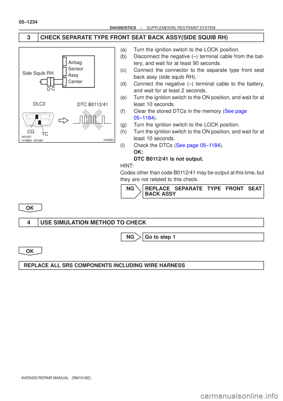
3CHECK SEPARATE TYPE FRONT SEAT BACK ASSY(SIDE SQUIB RH)
(a)Turn the ignition switch to the LOCK position.
(b)Disconnect the negative (±) terminal cable from the bat- tery, and wait for at least 90 seconds.
(c)Connect the connector to the separate type front seat back assy (side squib RH).
(d)Connect the negative (±) terminal cable to the battery, and wait for at least 2 seconds.
(e)Turn the ignition switch to the ON position, and wait for at least 10 seconds.
(f)Clear the stored DTCs in the memory (See page 05±1184).
(g)Turn the ignition switch to the LOCK position.
(h)Turn the ignition switch to the ON position, and wait for at least 10 seconds.
(i)Check the DTCs (See page 05±1184). OK:
DTC B0112/41 is not output.
HINT:
Codes other than code B0112/41 may be output at this time, but
they are not related to this check.
NG REPLACE SEPARATE TYPE FRONT SEAT BACK ASSY
OK
4 USE SIMULATION METHOD TO CHECK
NG Go to step 1
OK
REPLACE ALL SRS COMPONENTS INCLUDING WIRE HARNESS
Page 1260 of 5135
\b�����
\b����� \b�����\b�����H42850
Side Squib RH
SFR+
SFR±
DTC B0111/44
DLC3
CG TC Airbag
Sensor
Assy
Center
Floor Wire No.2
Service Wire
D
C
05±1230
±
DIAGNOSTICS SUPPLEMENTAL RESTRAINT SYSTEM
AVENSIS REPAIR MANUAL (RM1018E)
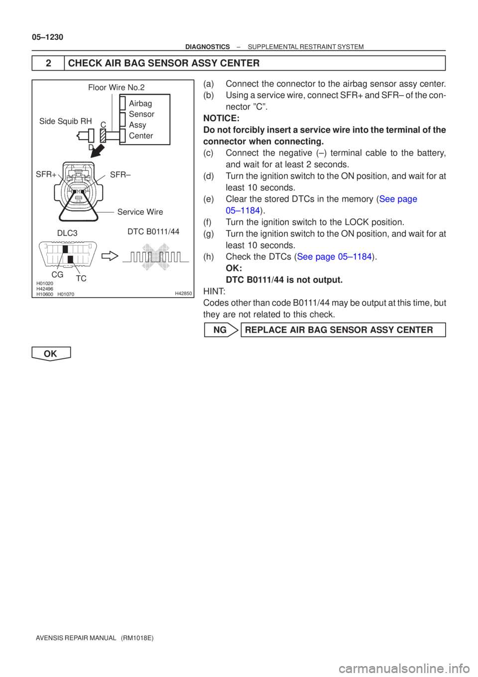
2 CHECK AIR BAG SENSOR ASSY CENTER
(a) Connect the connector to the airbag sensor assy center.
(b) Using a service wire, connect SFR+ and SFR± of the con- nector ºCº.
NOTICE:
Do not forcibly insert a service wire into the terminal of the
connector when connecting.
(c) Connect the negative (±) terminal cable to the battery, and wait for at least 2 seconds.
(d) Turn the ignition switch to the ON position, and wait for at least 10 seconds.
(e)Clear the stored DTCs in the memory (See page
05±1184).
(f) Turn the ignition switch to the LOCK position.
(g) Turn the ignition switch to the ON position, and wait for at least 10 seconds.
(h)Check the DTCs (See page 05±1184).
OK:
DTC B0111/44 is not output.
HINT:
Codes other than code B0111/44 may be output at this time, but
they are not related to this check.
NG REPLACE AIR BAG SENSOR ASSY CENTER
OK
Page 1261 of 5135
������
������������H40981
Side Squib RHDTC B0111/44
DLC3
CG TC Airbag
Sensor
Assy
Center
D C
±
DIAGNOSTICS SUPPLEMENTAL RESTRAINT SYSTEM
05±1231
AVENSIS REPAIR MANUAL (RM1018E)
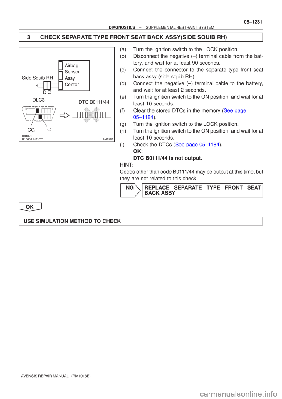
3CHECK SEPARATE TYPE FRONT SEAT BACK ASSY(SIDE SQUIB RH)
(a)Turn the ignition switch to the LOCK position.
(b)Disconnect the negative (±) terminal cable from the bat-
tery, and wait for at least 90 seconds.
(c)Connect the connector to the separate type front seat back assy (side squib RH).
(d)Connect the negative (±) terminal cable to the battery, and wait for at least 2 seconds.
(e)Turn the ignition switch to the ON position, and wait for at least 10 seconds.
(f)Clear the stored DTCs in the memory (See page 05±1184).
(g) Turn the ignition switch to the LOCK position.
(h) Turn the ignition switch to the ON position, and wait for at least 10 seconds.
(i)Check the DTCs (See page 05±1184). OK:
DTC B0111/44 is not output.
HINT:
Codes other than code B0111/44 may be output at this time, but
they are not related to this check.
NG REPLACE SEPARATE TYPE FRONT SEAT BACK ASSY
OK
USE SIMULATION METHOD TO CHECK
Page 1263 of 5135
\b����� \b�����
\b�����
H42849
Side Squib RHAirbag
Sensor
Assy
Center
SFR±
SFR+
Floor Wire No.2
A
B
C
D
\b�����\b�����\b�����H42111
Side Squib RH Airbag
Sensor
Assy
Center
CG TC
DLC3
DTC B0110/43
C
D
±
DIAGNOSTICS SUPPLEMENTAL RESTRAINT SYSTEM
05±1227
AVENSIS REPAIR MANUAL (RM1018E)
INSPECTION PROCEDURE
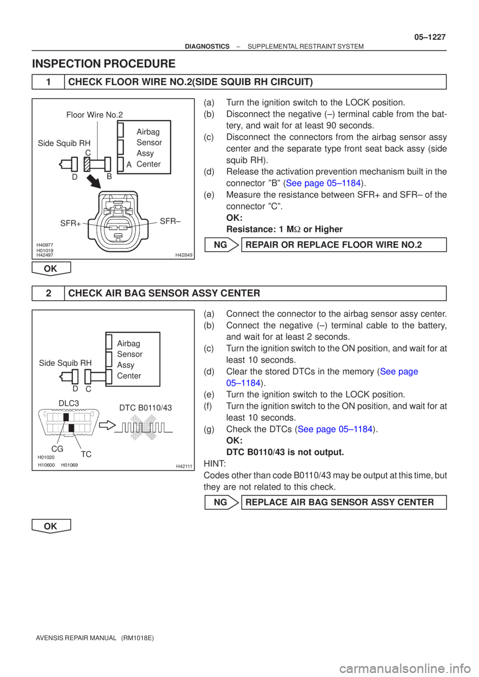
1CHECK FLOOR WIRE NO.2(SIDE SQUIB RH CIRCUIT)
(a)Turn the ignition switch to the LOCK position.
(b)Disconnect the negative (±) terminal cable from the bat-
tery, and wait for at least 90 seconds.
(c)Disconnect the connectors from the airbag sensor assy center and the separate type front seat back assy (side
squib RH).
(d)Release the activation prevention mechanism built in the
connector ºBº (See page 05±1184).
(e)Measure the resistance between SFR+ and SFR± of the connector ºCº.
OK:
Resistance: 1 M � or Higher
NGREPAIR OR REPLACE FLOOR WIRE NO.2
OK
2CHECK AIR BAG SENSOR ASSY CENTER
(a)Connect the connector to the airbag sensor assy center.
(b)Connect the negative (±) terminal cable to the battery, and wait for at least 2 seconds.
(c)Turn the ignition switch to the ON position, and wait for at least 10 seconds.
(d)Clear the stored DTCs in the memory (See page 05±1184).
(e) Turn the ignition switch to the LOCK position.
(f) Turn the ignition switch to the ON position, and wait for at
least 10 seconds.
(g)Check the DTCs (See page 05±1184). OK:
DTC B0110/43 is not output.
HINT:
Codes other than code B0110/43 may be output at this time, but
they are not related to this check.
NG REPLACE AIR BAG SENSOR ASSY CENTER
OK