Page 1195 of 5135
05C7U±01
I35990
Inspector 's name:
Customer 's NameVIN
Production Date
Licence No.
Odometer Readingkm
Miles Date vehicle
Brought In / /
Date of Problem Occurrence
How Often does Problem Occur?
Weather
Outdoor Temperature / /
� Continuous � Intermittent ( times a day)
� Fine � Cloudy � Snowy � Various / Other
� Hot � Warm � Cool � Cold (Approx.�F
�C)
DTC Check1st Time
2nd Time� Normal Code � Malfunction Code (Code )
� Normal Code � Malfunction Code (Code )
AIR CONDITIONING SYSTEM Check Sheet
± DIAGNOSTICSCOMBUSTION TYPE POWER HEATER SYSTEM
05±1163
AVENSIS REPAIR MANUAL (RM1018E)
CUSTOMER PROBLEM ANALYSIS CHECK
Page 1203 of 5135
05±1154
±
DIAGNOSTICS AIR CONDITIONING SYSTEM
AVENSIS REPAIR MANUAL (RM1018E)
1PERFORM ACTUATOR CHECK
(a)Set to actuator check mode (See page 05±1091).
(b) Press the DEF switch and change to step operation.
(c) Check the air flow temperature by hand.
Display codeRecirculation damper position
0FRESH
1FRESH
2FRESH
3FRESH
4RECIRCULATION
5RECIRCULATION
6RECIRCULATION
7RECIRCULATION
8RECIRCULATION
9RECIRCULATION
NG PROCEED TO NEXT CIRCUIT INSPECTION SHOWN ON PROBLEM SYMPTOMS TABLE
OK
Page 1207 of 5135
I36135
05±1152
±
DIAGNOSTICS AIR CONDITIONING SYSTEM
AVENSIS REPAIR MANUAL (RM1018E)
INSPECTION PROCEDURE
1PERFORM ACTUATOR CHECK
(a)Set the actuator check mode (See page 05±1091).
(b)Press the DEF switch and change to the step operation.
(c)Check the air flow level by hand.
Display CodeBlower level
0ON
1ON
2OFF
3OFF
4OFF
5OFF
6OFF
7OFF
8OFF
9OFF
OKPROCEED TO NEXT CIRCUIT INSPECTION SHOWN ON PROBLEM SYMPTOMS TABLE
NG
2INSPECT AIR CONDITIONER MAGNETIC VALVE
(a)Measure the resistance between terminals 1 and 2. Standard: 10 to 11 � at 25 �C (77 �F)
If the resistance is not as specified, replace the compressor
assy.
NGREPLACE W/PULLEY COMPRESSOR ASSY
OK
3CHECK HARNESS AND CONNECTOR(A/C AMPLIFIER ± BATTERY)
(a)Check for an open or short circuit in harness and connector between terminal \
SOL+ of A/C amplifier and battery + terminal (See page 01±32).
NG REPAIR OR REPLACE HARNESS ORCONNECTOR
OK
REPLACE AIR CONDITIONING AMPLIFIER
Page 1209 of 5135
I30151
2
1
LHD
RHD
±
DIAGNOSTICS AIR CONDITIONING SYSTEM
05±1149
AVENSIS REPAIR MANUAL (RM1018E)
INSPECTION PROCEDURE
1PERFORM ACTUATOR CHECK
(a)Set to actuator check mode (See page 05±1091).
(b)Press the DEF switch and change to step operation.
(c)Check the air flow level by hand.
Display CodeBlower level
00
11
216
316
416
516
616
716
816
931
OKPROCEED TO NEXT CIRCUIT INSPECTION
SHOWN ON PROBLEM SYMPTOMS TABLE
NG
2INSPECT BLOWER W/FAN MOTOR SUB±ASSY
(a)Connect the positive (+) lead from the battery to terminal 1 and negative (±) to terminal 2.
Standard: Blower motor operates smoothly.
If operation is not as specified, replace the blower motor.
NGREPLACE BLOWER W/FAN MOTOR SUB±ASSY
OK
3CHECK HARNESS AND CONNECTOR(BLOWER W/FAN MOTOR SUB±ASSY ± BLOWER MOTOR CONTROL)
(a)Check for an open or short circuit in harness and connector between blow\
er w/fan motor sub±assy
and blower motor control (See page 01±32).
NG REPAIR OR REPLACE HARNESS ORCONNECTOR
OK
Page 1215 of 5135
I35395
Fuse Block Center J/BA/C Control Assembly
ECU±B2
66
12CC CF 10 7
W±R W±R
A1624
+B
B±W
IE4 IP145
(*3) (*4)B±W Engine Room R/B No.1 & Engine Room J/B No.1B±G (*1)
B (*2) DCC
11A
1 21
Engine Room R/B No.3
Engine Room J/B No.4
Center J/B B (*2)
B±G (*1)B (*2)
B±G (*1) 33
4A 4B
CG CA W±B (*3) W±B (*3)11
63
A1613
GND
FL MAIN
Battery
IP IKAAA W±B (*4) W±B (*4)J17
J/C
*1: Gasoline
*2: 1CD±FTV*3: LHD
*4: RHDJ15
J/C 05±1142
± DIAGNOSTICSAIR CONDITIONING SYSTEM
AVENSIS REPAIR MANUAL (RM1018E)
BACK±UP POWER SOURCE CIRCUIT
CIRCUIT DESCRIPTION
This is the back±up power source for the A/C amplifier. Power is supplied even when the ignition switch is
off and is used for diagnostic trouble code memory etc.
WIRING DIAGRAM
050TW±10
Page 1218 of 5135

�����
����� \b����������H42104
D SquibAirbag
Sensor
Assy
Center
D±D+Spiral
Cable
Sub±assy
Color: Orange
TC
CG
DLC3 DTC B0101/14
Service Wire
C
D
E
F
±
DIAGNOSTICS SUPPLEMENTAL RESTRAINT SYSTEM
05±1203
AVENSIS REPAIR MANUAL (RM1018E)
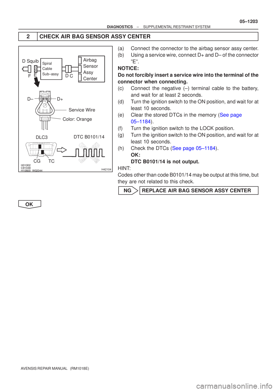
2CHECK AIR BAG SENSOR ASSY CENTER
(a)Connect the connector to the airbag sensor assy center.
(b)Using a service wire, connect D+ and D± of the connector
ºEº.
NOTICE:
Do not forcibly insert a service wire into the terminal of the
connector when connecting.
(c)Connect the negative (±) terminal cable to the battery, and wait for at least 2 seconds.
(d)Turn the ignition switch to the ON position, and wait for at least 10 seconds.
(e)Clear the stored DTCs in the memory (See page
05±1184).
(f) Turn the ignition switch to the LOCK position.
(g) Turn the ignition switch to the ON position, and wait for at least 10 seconds.
(h)Check the DTCs (See page 05±1184).
OK:
DTC B0101/14 is not output.
HINT:
Codes other than code B0101/14 may be output at this time, but
they are not related to this check.
NG REPLACE AIR BAG SENSOR ASSY CENTER
OK
Page 1219 of 5135

������������\b�����H40036
D SquibDLC3 DTC B0101/14
CG TCAirbag
Sensor
Assy
CenterSpiral
Cable
Sub±assy
C
D
E
F
������
��
��
������H41440
D Squib Airbag
Sensor
Assy
CenterSpiral
Cable
Sub±assy
Instrument Panel Wire
A
B
C
D
E
F
05±1204
±
DIAGNOSTICS SUPPLEMENTAL RESTRAINT SYSTEM
AVENSIS REPAIR MANUAL (RM1018E)
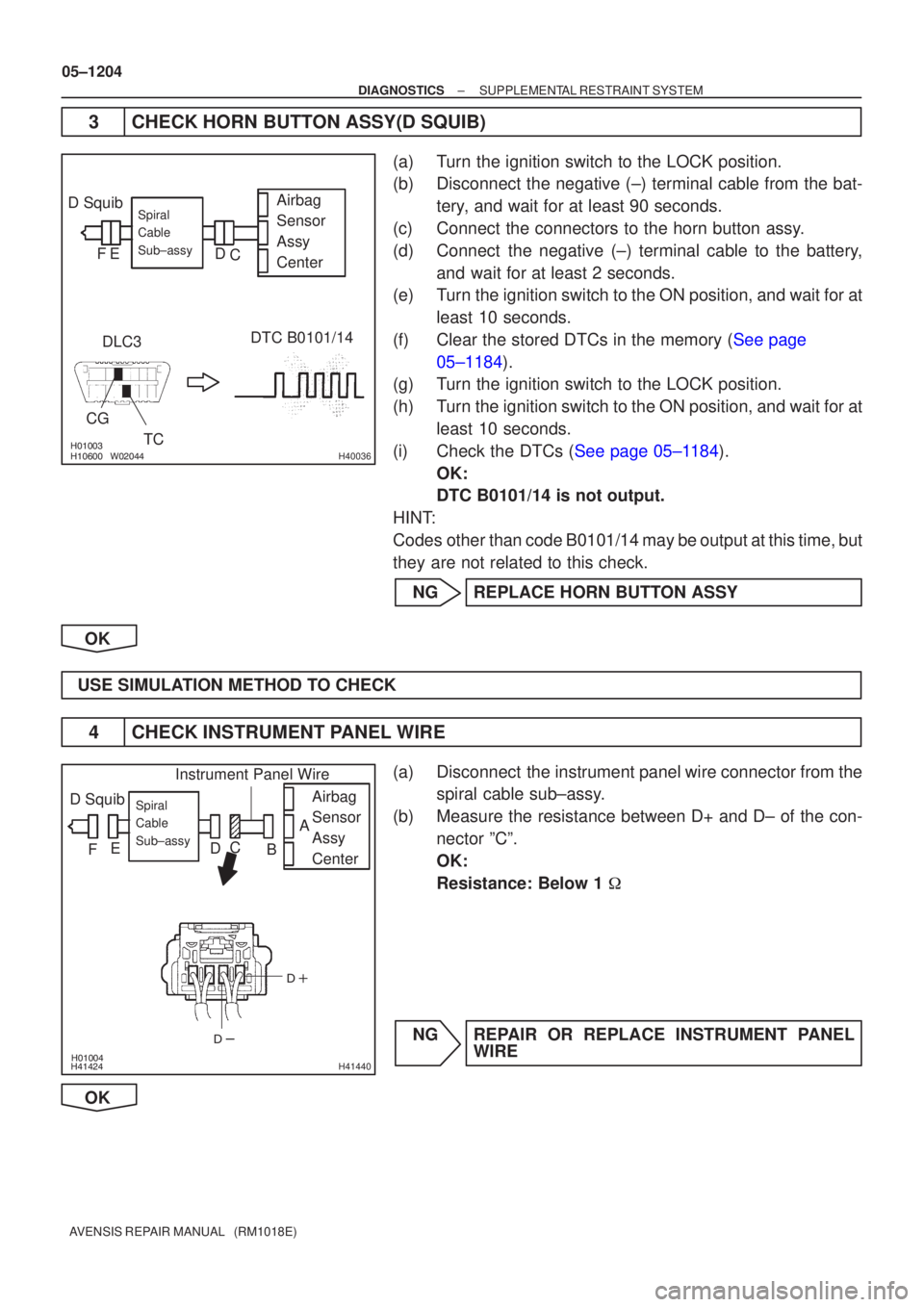
3CHECK HORN BUTTON ASSY(D SQUIB)
(a)Turn the ignition switch to the LOCK position.
(b)Disconnect the negative (±) terminal cable from the bat- tery, and wait for at least 90 seconds.
(c)Connect the connectors to the horn button assy.
(d)Connect the negative (±) terminal cable to the battery, and wait for at least 2 seconds.
(e)Turn the ignition switch to the ON position, and wait for at
least 10 seconds.
(f)Clear the stored DTCs in the memory (See page 05±1184).
(g) Turn the ignition switch to the LOCK position.
(h) Turn the ignition switch to the ON position, and wait for at
least 10 seconds.
(i)Check the DTCs (See page 05±1184). OK:
DTC B0101/14 is not output.
HINT:
Codes other than code B0101/14 may be output at this time, but
they are not related to this check.
NG REPLACE HORN BUTTON ASSY
OK
USE SIMULATION METHOD TO CHECK
4 CHECK INSTRUMENT PANEL WIRE
(a) Disconnect the instrument panel wire connector from the spiral cable sub±assy.
(b) Measure the resistance between D+ and D± of the con- nector ºCº.
OK:
Resistance: Below 1 �
NG REPAIR OR REPLACE INSTRUMENT PANEL WIRE
OK
Page 1223 of 5135

������������������H40030
D SquibAirbag
Sensor
Assy
Center
DLC3
CG TC DTC B0100/13Spiral
Cable
Sub±assy
C
D
E
F
������������������H40031
D Squib Airbag
Sensor
Assy
Center
DLC3
CG TC DTC B0100/13Spiral
Cable
Sub±assy
C
D
E
F
05±1200
±
DIAGNOSTICS SUPPLEMENTAL RESTRAINT SYSTEM
AVENSIS REPAIR MANUAL (RM1018E)
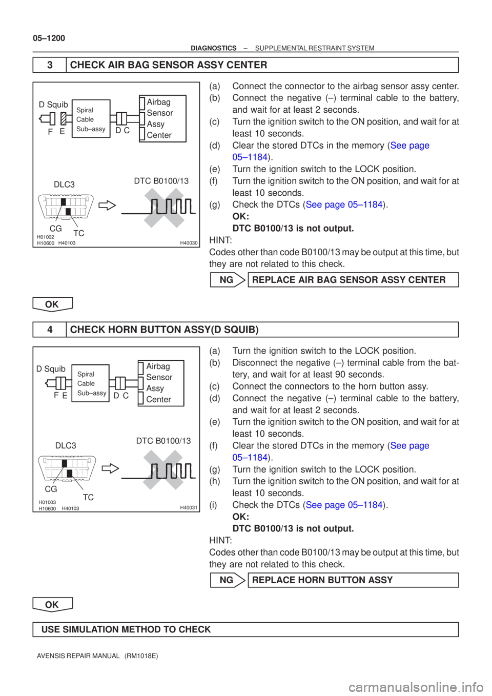
3CHECK AIR BAG SENSOR ASSY CENTER
(a)Connect the connector to the airbag sensor assy center.
(b)Connect the negative (±) terminal cable to the battery, and wait for at least 2 seconds.
(c)Turn the ignition switch to the ON position, and wait for at least 10 seconds.
(d)Clear the stored DTCs in the memory (See page 05±1184).
(e)Turn the ignition switch to the LOCK position.
(f)Turn the ignition switch to the ON position, and wait for at least 10 seconds.
(g)Check the DTCs (See page 05±1184).
OK:
DTC B0100/13 is not output.
HINT:
Codes other than code B0100/13 may be output at this time, but
they are not related to this check.
NGREPLACE AIR BAG SENSOR ASSY CENTER
OK
4CHECK HORN BUTTON ASSY(D SQUIB)
(a)Turn the ignition switch to the LOCK position.
(b)Disconnect the negative (±) terminal cable from the bat- tery, and wait for at least 90 seconds.
(c)Connect the connectors to the horn button assy.
(d)Connect the negative (±) terminal cable to the battery, and wait for at least 2 seconds.
(e)Turn the ignition switch to the ON position, and wait for at
least 10 seconds.
(f)Clear the stored DTCs in the memory (See page 05±1184).
(g) Turn the ignition switch to the LOCK position.
(h) Turn the ignition switch to the ON position, and wait for at least 10 seconds.
(i)Check the DTCs (See page 05±1184). OK:
DTC B0100/13 is not output.
HINT:
Codes other than code B0100/13 may be output at this time, but
they are not related to this check.
NG REPLACE HORN BUTTON ASSY
OK
USE SIMULATION METHOD TO CHECK