Page 1113 of 5135
I35392
DTCDEF
I35417ECU±B2
Fuse block:
3
2
145678
910111213141516
DLC3
A04550
05±1092
±
DIAGNOSTICS AIR CONDITIONING SYSTEM
AVENSIS REPAIR MANUAL (RM1018E)
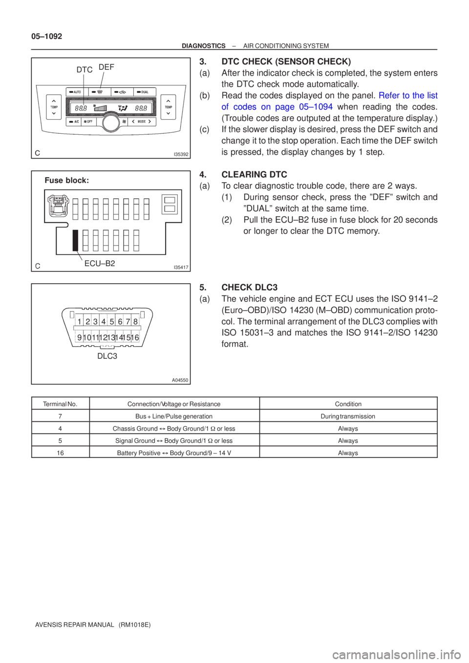
3.DTC CHECK (SENSOR CHECK)
(a)After the indicator check is completed, the system enters the DTC check mode automatically.
(b)Read the codes displayed on the panel. Refer to the list of codes on page 05±1094 when reading the codes.
(Trouble codes are outputed at the temperature display.)
(c) If the slower display is desired, press the DEF switch and
change it to the stop operation. Each time the DEF switch
is pressed, the display changes by 1 step.
4. CLEARING DTC
(a) To clear diagnostic trouble code, there are 2 ways. (1) During sensor check, press the ºDEFº switch andºDUALº switch at the same time.
(2) Pull the ECU±B2 fuse in fuse block for 20 seconds or longer to clear the DTC memory.
5. CHECK DLC3
(a) The vehicle engine and ECT ECU uses the ISO 9141±2 (Euro±OBD)/ISO 14230 (M±OBD) communication proto-
col. The terminal arrangement of the DLC3 complies with
ISO 15031±3 and matches the ISO 9141±2/ISO 14230
format.
Terminal No.Connection/Voltage or ResistanceCondition
7Bus + Line/Pulse generationDuring transmission
4Chassis Ground � Body Ground/1 � or lessAlways
5Signal Ground � Body Ground/1 � or lessAlways
16Battery Positive � Body Ground/9 ± 14 VAlways
Page 1114 of 5135
I36146
Display code R/FDEFLHD:
I36147
Display code RHD:R/FDEF
Blower level Step No.Display
codeConditions
Air flow bent Air inlet damper Compressor
ºCOOLº side (Full closed)Air mix damper
OFF FRESH
FACE 0
1
2
3
6
7
8
9
104
51
16
16
16
16
16
16
16
31 0
1
2
3
6
7
8 4
5
9FACE
FACE
FACE
B/L
FOOT1
FOOT/ DEF.
DEF.FRESH
ON
ON
ON
ON
ON
ON
ONºCOOLº side (Full closed)
ºCOOLº side (Full closed)
ºCOOLº side (Full closed)
ºCOOLº/ ºHOT º (50 % open)
ºHOTº side (Full opened)
FOOT FACE1FRESH
FRESH
RECIRCULATION
RECIRCULATION
RECIRCULATION
RECIRCULATION
RECIRCULATION
RECIRCULATIONHot gas magnetic valve
ºCOOLº/ ºHOT º (50 % open)
ºHOTº side (Full opened)
ºHOTº side (Full opened)ON
ON
OFF
OFF
OFF
OFF
OFF
OFF
OFF
OFF OFF
ºHOTº side (Full opened) OFF
± DIAGNOSTICSAIR CONDITIONING SYSTEM
05±1093
AVENSIS REPAIR MANUAL (RM1018E)
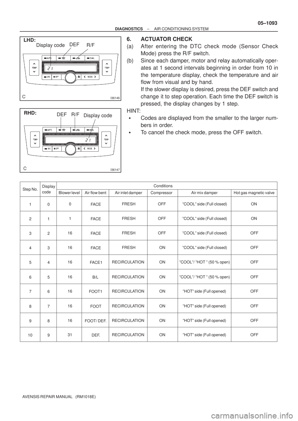
6. ACTUATOR CHECK
(a) After entering the DTC check mode (Sensor Check
Mode) press the R/F switch.
(b) Since each damper, motor and relay automatically oper-
ates at 1 second intervals beginning in order from 10 in
the temperature display, check the temperature and air
flow from visual and by hand.
If the slower display is desired, press the DEF switch and
change it to step operation. Each time the DEF switch is
pressed, the display changes by 1 step.
HINT:
�Codes are displayed from the smaller to the larger num-
bers in order.
�To cancel the check mode, press the OFF switch.
Page 1115 of 5135
050TH±09
I30150
Inspector 's name:
Customer 's NameVIN
Production Date
Licence No.
Odometer Readingkm
Miles Date vehicle
Brought In / /
Date of Problem Occurrence
How Often does Problem Occur?
Weather
Outdoor Temperature / /
� Continuous � Intermittent ( times a day)
� Fine � Cloudy � Snowy � Various / Other
� Hot � Warm � Cool � Cold (Approx.�F
�C)
Symptoms� Blower motor does not operate
� Blower motor speed does not change
(Always Hi, Always Mid, Always Lo) Air Flow Control
Faulty
� Cabin temperature does not go down
� Response is slow
� Cannot change between FRS and REC
(Always Fresh or always Recirculating)
� Will not enter the desired mode Temperature
Control Faulty
Air Inlet Control
Faulty
Vent Control
Faulty
DTC Check1st Time
2nd Time� Normal Code � Malfunction Code (Code )
� Normal Code � Malfunction Code (Code )
AIR CONDITIONING SYSTEM Check Sheet
� Cabin temperature does not rise
� Mode will not change 05±1090
± DIAGNOSTICSAIR CONDITIONING SYSTEM
AVENSIS REPAIR MANUAL (RM1018E)
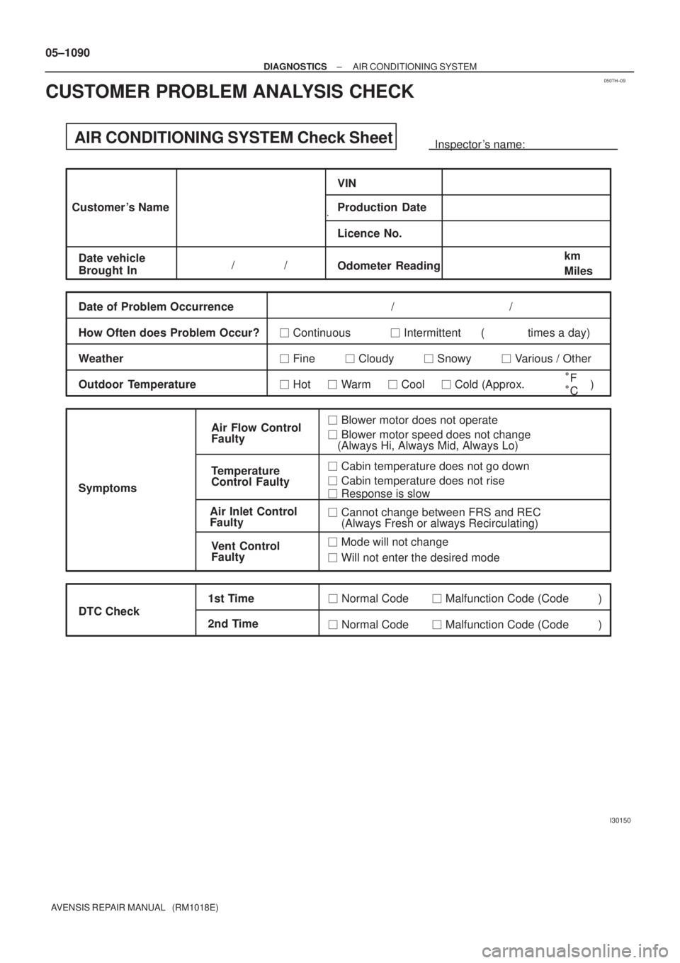
CUSTOMER PROBLEM ANALYSIS CHECK
Page 1116 of 5135
050TG±11
05±1088
±
DIAGNOSTICS AIR CONDITIONING SYSTEM
AVENSIS REPAIR MANUAL (RM1018E)
AIR CONDITIONING SYSTEM
HOW TO PROCEED WITH TROUBLESHOOTING
1VEHICLE BROUGHT TO WORK SHOP
2CUSTOMER PROBLEM ANALYSIS (See page 05±1090)
3CHECK AND CLEAR DTC (See page 05±1091)
4 PROBLEM SYMPTOM CONFIRMATION
SYMPTOM OCCUR (GO TO STEP 6)
SYMPTOM DOES NOT OCCUR (GO TO
STEP 5)
5SYMPTOM SIMULATION (See page 01±22)
6DTC CHECK (See page 05±1091)
MALFUNCTION CODE (GO TO STEP 7)
NORMAL CODE (GO TO STEP 8)
7DTC CHART (See page 05±1094)
GO TO STEP 10
8PROBLEM SYMPTOMS TABLE (See page 05±1100)
9ACTUATOR CHECK (See page 05±1091)
Page 1125 of 5135
F44304
PGND (±)
E14PIG (+)
±
DIAGNOSTICS ELECTRONIC MOTOR POWER STEERING SYSTEM
05±1081
AVENSIS REPAIR MANUAL (RM1018E)
INSPECTION PROCEDURE
NOTICE:
When performing the inspection of power steering ECU, ECU must be instal\
led to the vehicle or fully
fixed.
HINT:
Start the inspection from the step 1 with using hand±held tester. Start from step 2 without using hand±held
tester.
1READ VALUE OF HAND±HELD TESTER
(a)Connect the hand±held tester to the DLC3.
(b)Turn the ignition switch to ON and turn the hand±held tester main swit\
ch to ON.
(c)Select the item ºPIG SUPPLYº in the FREEZE FRAME DATA and read its value displayed on the hand±
held tester.
(d)Check that the power supply voltage value of the drive motor displayed b\
y the hand±held tester. Standard:
Voltage: 10 to 16 V
OKGo to step 3
NG
GO TO RELEVANT DTC CHART
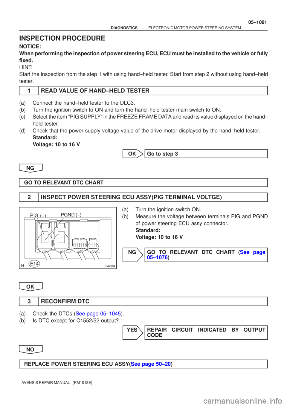
2INSPECT POWER STEERING ECU ASSY(PIG TERMINAL VOLTGE)
(a)Turn the ignition switch ON.
(b)Measure the voltage between terminals PIG and PGND of power steering ECU assy connector.
Standard:
Voltage: 10 to 16 V
NGGO TO RELEVANT DTC CHART (See page 05±1076)
OK
3 RECONFIRM DTC
(a)Check the DTCs (See page 05±1045).
(b) Is DTC except for C1552/52 output? YES REPAIR CIRCUIT INDICATED BY OUTPUTCODE
NO
REPLACE POWER STEERING ECU ASSY(See page 50±20)
Page 1134 of 5135
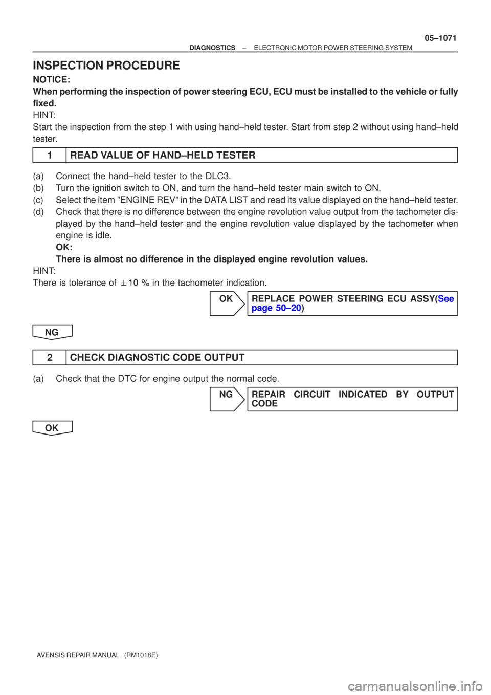
±
DIAGNOSTICS ELECTRONIC MOTOR POWER STEERING SYSTEM
05±1071
AVENSIS REPAIR MANUAL (RM1018E)
INSPECTION PROCEDURE
NOTICE:
When performing the inspection of power steering ECU, ECU must be instal\
led to the vehicle or fully
fixed.
HINT:
Start the inspection from the step 1 with using hand±held tester. Start from step 2 without using hand±held
tester.
1READ VALUE OF HAND±HELD TESTER
(a)Connect the hand±held tester to the DLC3.
(b)Turn the ignition switch to ON, and turn the hand±held tester main swi\
tch to ON.
(c)Select the item ºENGINE REVº in the DATA LIST and read its value displayed on the hand±held tester.
(d)Check that there is no difference between the engine revolution value output from the tachometer d\
is-
played by the hand±held tester and the engine revolution value displayed by\
the tachometer when
engine is idle.
OK:
There is almost no difference in the displayed engine revolution values.\
HINT:
There is tolerance of �10 % in the tachometer indication.
OKREPLACE POWER STEERING ECU ASSY(Seepage 50±20)
NG
2 CHECK DIAGNOSTIC CODE OUTPUT
(a) Check that the DTC for engine output the normal code. NG REPAIR CIRCUIT INDICATED BY OUTPUTCODE
OK
Page 1137 of 5135
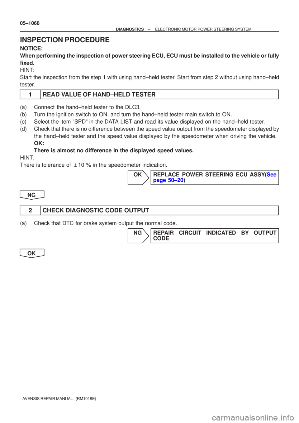
05±1068
±
DIAGNOSTICS ELECTRONIC MOTOR POWER STEERING SYSTEM
AVENSIS REPAIR MANUAL (RM1018E)
INSPECTION PROCEDURE
NOTICE:
When performing the inspection of power steering ECU, ECU must be instal\
led to the vehicle or fully
fixed.
HINT:
Start the inspection from the step 1 with using hand±held tester. Start from step 2 without using hand±held
tester.
1READ VALUE OF HAND±HELD TESTER
(a)Connect the hand±held tester to the DLC3.
(b)Turn the ignition switch to ON, and turn the hand±held tester main swi\
tch to ON.
(c)Select the item ºSPDº in the DATA LIST and read its value displayed on the hand±held tester.
(d)Check that there is no difference between the speed value output from the speedometer displayed by the hand±held tester and the speed value displayed by the speedometer wh\
en driving the vehicle.
OK:
There is almost no difference in the displayed speed values.
HINT:
There is tolerance of �10 % in the speedometer indication.
OKREPLACE POWER STEERING ECU ASSY(Seepage 50±20)
NG
2 CHECK DIAGNOSTIC CODE OUTPUT
(a) Check that DTC for brake system output the normal code. NG REPAIR CIRCUIT INDICATED BY OUTPUTCODE
OK
Page 1139 of 5135
05±1066
±
DIAGNOSTICS ELECTRONIC MOTOR POWER STEERING SYSTEM
AVENSIS REPAIR MANUAL (RM1018E)
DTCC1531/31EMPS ECU Circuit Malfunction
DTCC1532/32EMPS ECU Circuit Malfunction
DTCC1533/33EMPS ECU Circuit Malfunction
DTCC1534/34EMPS ECU Circuit Malfunction
DTCC1581/81Assist Map Un±written
CIRCUIT DESCRIPTION
DTC No.DTC Detecting ConditionTrouble Area
C1531/31
C1532/32PoersteeringECUassmalfnctionC1533/33Power steering ECU assy malfunctionPower steering ECU assy
C1534/34
gy
C1581/81Assist map un±written
INSPECTION PROCEDURE
1RECONFIRM DTC
(a)Check the DTCs (See page 05±1045).
(b) Is DTC except for C1531/31, C1532/32, C1533/33, C1534/34 and/or C1581/81\
output? YES REPAIR CIRCUIT INDICATED BY OUTPUTCODE
NO
REPLACE POWER STEERING ECU ASSY (See page 50±20)
050WS±04