Page 3537 of 5135
C67604
D30525
D30526
SST
D30527
D30528
± MANUAL TRANSMISSION/TRANSAXLEMANUAL TRANSAXLE ASSY (C250)
41±5
C250 M/T REPAIR MANUAL (RM1020E)
6. REMOVE RELEASE FORK SUPPORT
(a) Remove the clutch release fork support from the front
transaxle case.
7. REMOVE CLUTCH RELEASE FORK BOOT
(a) Remove the clutch release fork boot from the front trans-
axle case.
8. REMOVE BACK UP LAMP SWITCH ASSY
(a) Using SST, remove the back±up lamp switch assy and
gasket from the manual transmission case.
SST 09817±16011
9. REMOVE FLOOR SHIFT CONTROL LEVER HOUSING
SUPPORT BRACKET
(a) Remove the 3 bolts and control cable bracket from the
front transaxle case.
10. REMOVE SELECTING BELL CRANK ASSY
(a) Remove the 2 bolts and selecting bell crank assy from the
manual transmission case.
Page 3540 of 5135
Q06512
D30535
C80343
C80344
C80345
41±8
± MANUAL TRANSMISSION/TRANSAXLEMANUAL TRANSAXLE ASSY (C250)
C250 M/T REPAIR MANUAL (RM1020E)
(b) Engage the gear to the double meshing.
(c) Remove the manual transmission output shaft rear set
nut.
(d) Disengage the double meshing of the gear.
18. REMOVE GEAR SHIFT FORK NO.3
(a) Remove the shift fork set bolt from the gear shift fork
No.3.
(b) Remove the No.3 hub sleeve and gear shift fork No.3 from
the transmission clutch hub No.3.
19. INSPECT 5TH GEAR THRUST CLEARANCE
(a) Using a dial indicator, measure the thrust clearance.
Standard clearance:
0.10 ± 0.57 mm (0.0039 ± 0.0224 in.)
Maximum clearance:
0.57 mm (0.0224 in.)
20. INSPECT 5TH GEAR RADIAL CLEARANCE
(a) Using a dial indicator, measure the radial clearance.
Standard clearance:
0.015 ± 0.058 mm (0.0006 ± 0.0023 in.)
Maximum clearance:
0.058 mm (0.0023 in.)
If the clearance exceeds the maximum, replace the gear needle
roller bearing or shaft.
Page 3541 of 5135
D30536
C80347
SST
D07737
D30537
D30538
SST
± MANUAL TRANSMISSION/TRANSAXLEMANUAL TRANSAXLE ASSY (C250)
41±9
C250 M/T REPAIR MANUAL (RM1020E)
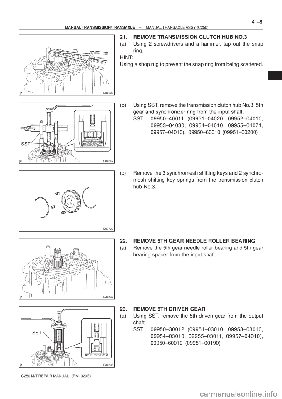
21. REMOVE TRANSMISSION CLUTCH HUB NO.3
(a) Using 2 screwdrivers and a hammer, tap out the snap
ring.
HINT:
Using a shop rug to prevent the snap ring from being scattered.
(b) Using SST, remove the transmission clutch hub No.3, 5th
gear and synchronizer ring from the input shaft.
SST 09950±40011 (09951±04020, 09952±04010,
09953±04030, 09954±04010, 09955±04071,
09957±04010), 09950±60010 (09951±00200)
(c) Remove the 3 synchromesh shifting keys and 2 synchro-
mesh shifting key springs from the transmission clutch
hub No.3.
22. REMOVE 5TH GEAR NEEDLE ROLLER BEARING
(a) Remove the 5th gear needle roller bearing and 5th gear
bearing spacer from the input shaft.
23. REMOVE 5TH DRIVEN GEAR
(a) Using SST, remove the 5th driven gear from the output
shaft.
SST 09950±30012 (09951±03010, 09953±03010,
09954±03010, 09955±03011, 09957±04010),
09950±60010 (09951±00190)
Page 3551 of 5135
C67850
C67978
C80375
± MANUAL TRANSMISSION/TRANSAXLEMANUAL TRANSAXLE ASSY (C250)
41±19
C250 M/T REPAIR MANUAL (RM1020E)
NOTICE:
Ensure the fine lapping compound is completely washed
off after rubbing.
(c) Check again the breaking effect of the synchronizer ring.
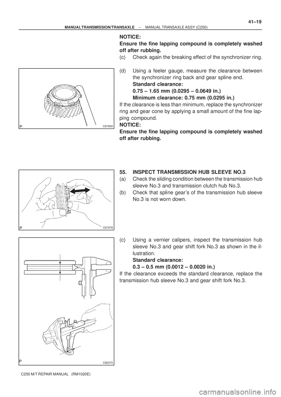
(d) Using a feeler gauge, measure the clearance between
the synchronizer ring back and gear spline end.
Standard clearance:
0.75 ± 1.65 mm (0.0295 ± 0.0649 in.)
Minimum clearance: 0.75 mm (0.0295 in.)
If the clearance is less than minimum, replace the synchronizer
ring and gear cone by applying a small amount of the fine lap-
ping compound.
NOTICE:
Ensure the fine lapping compound is completely washed
off after rubbing.
55. INSPECT TRANSMISSION HUB SLEEVE NO.3
(a) Check the sliding condition between the transmission hub
sleeve No.3 and transmission clutch hub No.3.
(b) Check that spline gear's of the transmission hub sleeve
No.3 is not worn down.
(c) Using a vernier calipers, inspect the transmission hub
sleeve No.3 and gear shift fork No.3 as shown in the il-
lustration.
Standard clearance:
0.3 ± 0.5 mm (0.0012 ± 0.0020 in.)
If the clearance exceeds the standard clearance, replace the
transmission hub sleeve No.3 and gear shift fork No.3.
Page 3563 of 5135
D30550
Engine
Side
D30551
Key Position
C80400
C80344
± MANUAL TRANSMISSION/TRANSAXLEMANUAL TRANSAXLE ASSY (C250)
41±31
C250 M/T REPAIR MANUAL (RM1020E)
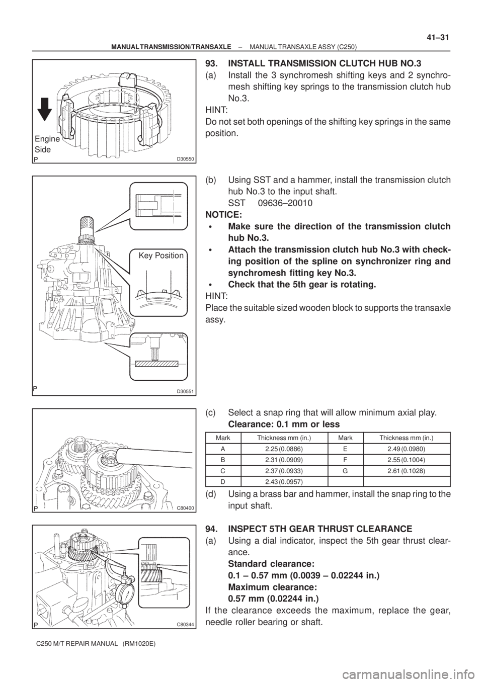
93. INSTALL TRANSMISSION CLUTCH HUB NO.3
(a) Install the 3 synchromesh shifting keys and 2 synchro-
mesh shifting key springs to the transmission clutch hub
No.3.
HINT:
Do not set both openings of the shifting key springs in the same
position.
(b) Using SST and a hammer, install the transmission clutch
hub No.3 to the input shaft.
SST 09636±20010
NOTICE:
�Make sure the direction of the transmission clutch
hub No.3.
�Attach the transmission clutch hub No.3 with check-
ing position of the spline on synchronizer ring and
synchromesh fitting key No.3.
�Check that the 5th gear is rotating.
HINT:
Place the suitable sized wooden block to supports the transaxle
assy.
(c) Select a snap ring that will allow minimum axial play.
Clearance: 0.1 mm or less
MarkThickness mm (in.)MarkThickness mm (in.)
A2.25 (0.0886)E2.49 (0.0980)
B2.31 (0.0909)F2.55 (0.1004)
C2.37 (0.0933)G2.61 (0.1028)
D2.43 (0.0957)
(d) Using a brass bar and hammer, install the snap ring to the
input shaft.
94. INSPECT 5TH GEAR THRUST CLEARANCE
(a) Using a dial indicator, inspect the 5th gear thrust clear-
ance.
Standard clearance:
0.1 ± 0.57 mm (0.0039 ± 0.02244 in.)
Maximum clearance:
0.57 mm (0.02244 in.)
If the clearance exceeds the maximum, replace the gear,
needle roller bearing or shaft.
Page 3564 of 5135
C80345
C80401
C80402
C80403
C80404
41±32
± MANUAL TRANSMISSION/TRANSAXLEMANUAL TRANSAXLE ASSY (C250)
C250 M/T REPAIR MANUAL (RM1020E)
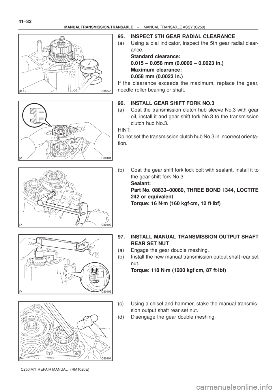
95. INSPECT 5TH GEAR RADIAL CLEARANCE
(a) Using a dial indicator, inspect the 5th gear radial clear-
ance.
Standard clearance:
0.015 ± 0.058 mm (0.0006 ± 0.0023 in.)
Maximum clearance:
0.058 mm (0.0023 in.)
If the clearance exceeds the maximum, replace the gear,
needle roller bearing or shaft.
96. INSTALL GEAR SHIFT FORK NO.3
(a) Coat the transmission clutch hub sleeve No.3 with gear
oil, install it and gear shift fork No.3 to the transmission
clutch hub No.3.
HINT:
Do not set the transmission clutch hub No.3 in incorrect orienta-
tion.
(b) Coat the gear shift fork lock bolt with sealant, install it to
the gear shift fork No.3.
Sealant:
Part No. 08833±00080, THREE BOND 1344, LOCTITE
242 or equivalent
Torque: 16 N�m (160 kgf�cm, 12 ft�lbf)
97. INSTALL MANUAL TRANSMISSION OUTPUT SHAFT
REAR SET NUT
(a) Engage the gear double meshing.
(b) Install the new manual transmission output shaft rear set
nut.
Torque: 118 N�m (1200 kgf�cm, 87 ft�lbf)
(c) Using a chisel and hammer, stake the manual transmis-
sion output shaft rear set nut.
(d) Disengage the gear double meshing.
Page 3567 of 5135
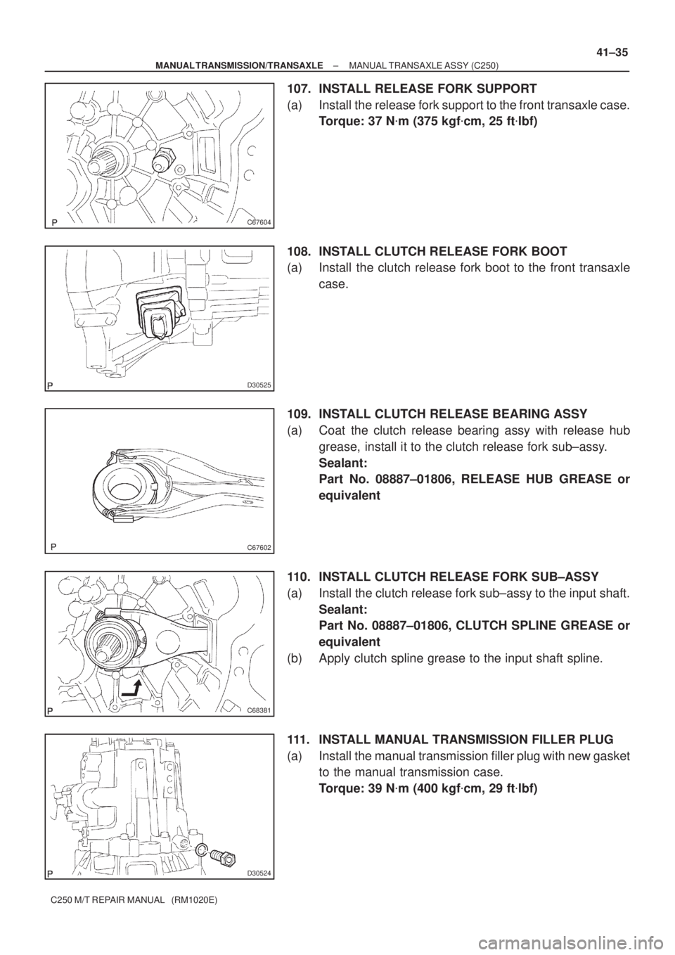
C67604
D30525
C67602
C68381
D30524
± MANUAL TRANSMISSION/TRANSAXLEMANUAL TRANSAXLE ASSY (C250)
41±35
C250 M/T REPAIR MANUAL (RM1020E)
107. INSTALL RELEASE FORK SUPPORT
(a) Install the release fork support to the front transaxle case.
Torque: 37 N�m (375 kgf�cm, 25 ft�lbf)
108. INSTALL CLUTCH RELEASE FORK BOOT
(a) Install the clutch release fork boot to the front transaxle
case.
109. INSTALL CLUTCH RELEASE BEARING ASSY
(a) Coat the clutch release bearing assy with release hub
grease, install it to the clutch release fork sub±assy.
Sealant:
Part No. 08887±01806, RELEASE HUB GREASE or
equivalent
110. INSTALL CLUTCH RELEASE FORK SUB±ASSY
(a) Install the clutch release fork sub±assy to the input shaft.
Sealant:
Part No. 08887±01806, CLUTCH SPLINE GREASE or
equivalent
(b) Apply clutch spline grease to the input shaft spline.
111. INSTALL MANUAL TRANSMISSION FILLER PLUG
(a) Install the manual transmission filler plug with new gasket
to the manual transmission case.
Torque: 39 N�m (400 kgf�cm, 29 ft�lbf)
Page 3589 of 5135
9808R±01
± COMPONENTS151350
98±5
3507/BRAKE BAND & MULTIPLE DISC CLUTCH (ATM)
(0008± )NZE121..ATM U340E