Page 2589 of 5135

G23175
G23220
32±10
±
BRAKE BRAKE PEDAL SUB±ASSY
AVENSIS REPAIR MANUAL (RM1018E)
8. INSTALL BRAKE PEDAL SUB±ASSY
(a) Apply lithium soap base glycol grease to the inside surface of 2 new bus\
hes.
(b) Install the brake pedal sub±assy and 2 bushes to the brake pedal supp\
ort sub±assy with the brake pedal shaft and nut.
Torque: 37 N �m (375 kgf �cm, 27 ft �lbf)
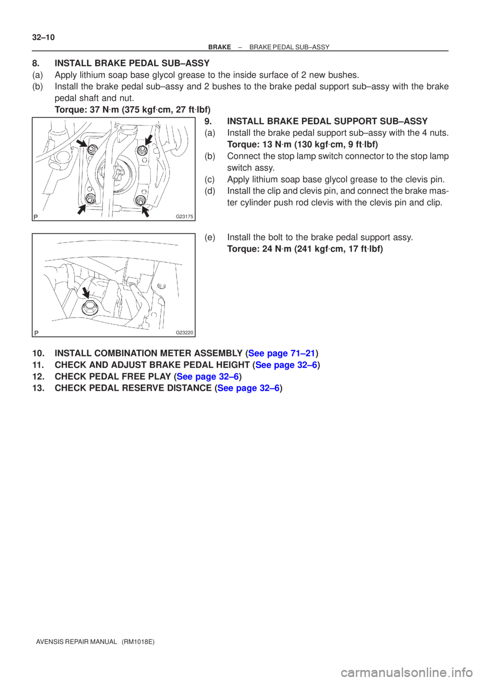
9. INSTALL BRAKE PEDAL SUPPORT SUB±ASSY
(a) Install the brake pedal support sub±assy with the 4 nuts. Torque: 13 N �m (130 kgf �cm, 9 ft �lbf)
(b) Connect the stop lamp switch connector to the stop lamp switch assy.
(c) Apply lithium soap base glycol grease to the clevis pin.
(d) Install the clip and clevis pin, and connect the brake mas- ter cylinder push rod clevis with the clevis pin and clip.
(e) Install the bolt to the brake pedal support assy. Torque: 24 N �m (241 kgf �cm, 17 ft �lbf)
10.INSTALL COMBINATION METER ASSEMBLY (See page 71±21)
11.CHECK AND ADJUST BRAKE PEDAL HEIGHT (See page 32±6)
12.CHECK PEDAL FREE PLAY (See page 32±6)
13.CHECK PEDAL RESERVE DISTANCE (See page 32±6)
Page 2590 of 5135
320G0±02
G23174
Clip
Clevis Pin
Brake Pedal
Support Sub±assy
� Bush
� Bush
Brake Pedal Sub±assyStop Lamp Switch Connector
Stop Lamp Switch assy
Brake Pedal Sub±assy
Brake Pedal Pad
Brake Pedal Pad
Lithium soap base glycol grease
37 (375, 27)
24 (241, 17)
� Non±reusable part
N�m (kgf�cm, ft�lbf)
: Specified torque A/T models:Brake Master Cylinder
Push Rod Clevis
13 (130, 9)
13 (130, 9)
Stop Lamp Switch Mounting Adjuster
Brake pedal shaft M/T models: 32±8
± BRAKEBRAKE PEDAL SUB±ASSY
AVENSIS REPAIR MANUAL (RM1018E)
COMPONENTS
Page 2591 of 5135

320VI±01
G23173
Stop Lamp Switch Assy
Push Rod
Pedal Height
F43108
Stop Lamp Switch Assy Cushion
1.5 ± 2.5 mm (0.059 ± 0.098 in.) 32±6
± BRAKEBRAKE PEDAL SUB±ASSY
AVENSIS REPAIR MANUAL (RM1018E)
BRAKE PEDAL SUB±ASSY
ADJUSTMENT
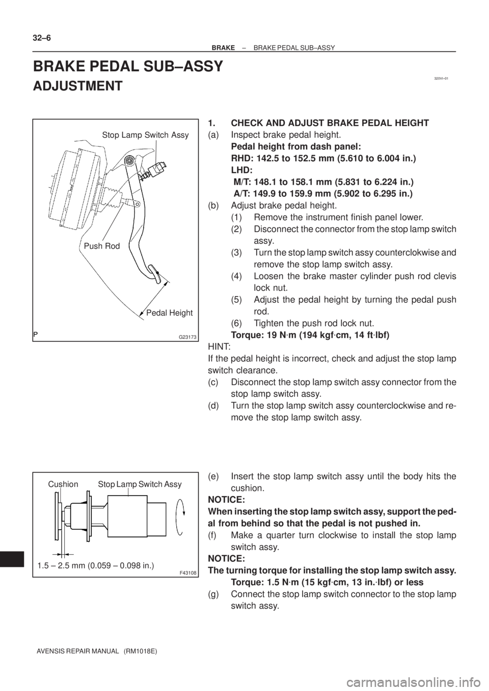
1. CHECK AND ADJUST BRAKE PEDAL HEIGHT
(a) Inspect brake pedal height.
Pedal height from dash panel:
RHD: 142.5 to 152.5 mm (5.610 to 6.004 in.)
LHD:
M/T: 148.1 to 158.1 mm (5.831 to 6.224 in.)
A/T: 149.9 to 159.9 mm (5.902 to 6.295 in.)
(b) Adjust brake pedal height.
(1) Remove the instrument finish panel lower.
(2) Disconnect the connector from the stop lamp switch
assy.
(3) Turn the stop lamp switch assy counterclokwise and
remove the stop lamp switch assy.
(4) Loosen the brake master cylinder push rod clevis
lock nut.
(5) Adjust the pedal height by turning the pedal push
rod.
(6) Tighten the push rod lock nut.
Torque: 19 N�m (194 kgf�cm, 14 ft�lbf)
HINT:
If the pedal height is incorrect, check and adjust the stop lamp
switch clearance.
(c) Disconnect the stop lamp switch assy connector from the
stop lamp switch assy.
(d) Turn the stop lamp switch assy counterclockwise and re-
move the stop lamp switch assy.
(e) Insert the stop lamp switch assy until the body hits the
cushion.
NOTICE:
When inserting the stop lamp switch assy, support the ped-
al from behind so that the pedal is not pushed in.
(f) Make a quarter turn clockwise to install the stop lamp
switch assy.
NOTICE:
The turning torque for installing the stop lamp switch assy.
Torque: 1.5 N�m (15 kgf�cm, 13 in.�lbf) or less
(g) Connect the stop lamp switch connector to the stop lamp
switch assy.
Page 2592 of 5135
G23176
Pedal Free Play
R00934
Pedal Reserve
Distance
± BRAKEBRAKE PEDAL SUB±ASSY
32±7
AVENSIS REPAIR MANUAL (RM1018E)
(h) Check the protrusion of the rod.
Protrusion of the rod: 0.5 to 2.6 mm (0.020 to 0.102 in.)
(i) Install the clevis pin and clip.
(j) After adjusting the pedal height, check the pedal free
play.
2. CHECK PEDAL FREE PLAY
(a) Stop the engine and depress the brake pedal several
times until there is no more vacuum left in the booster.
(b) Push in the pedal until the beginning of the resistance is
felt. Measure the distance, as shown.
Pedal free play: 1 to 6 mm (0.04 to 0.24 in.)
3. CHECK PEDAL RESERVE DISTANCE
(a) Release the parking brake lever.
With the engine running, depress the pedal and measure
the pedal reserve distance, as shown.
Pedal reserve distance from asphalt sheet at 490 N
(50 kgf, 110.2 lbf): More than 50 mm (1.97 in.)
If the distance is out of the specification , troubleshoot the brake
system.
Page 2593 of 5135
3201C±08
G24222
G24223
G24224
32±4
± BRAKEBRAKE FLUID
AVENSIS REPAIR MANUAL (RM1018E)
BRAKE FLUID
BLEEDING
NOTICE:
Wash the brake fluid off immediately if it adheres to any painted surfaces.
HINT:
When working on the brake system or when air in the brake lines is suspected, bleed the air from the system.
1. FILL RESERVOIR WITH BRAKE FLUID
Fluid: SAE J1704 or FMVSS No. 116 DOT4
2. BLEED MASTER CYLINDER
HINT:
After disassembling the master cylinder or when the reservoir
becomes empty, bleed the air out of the brake master cylinder.
(a) w/o VSC:
Using SST, Disconnect the brake lines from the brake
master cylinder.
SST 09023±00100
(b) w/ VSC:
Using SST, Disconnect the brake lines from the brake
master cylinder.
SST 09023±38400
(c) Slowly depress and hold the brake pedal it.
(d) Cover off the outer holes with your fingers, and release
the brake pedal.
(e) Repeat (b) and (c) 3 or 4 times.
Page 2594 of 5135
F42258
G24222
± BRAKEBRAKE FLUID
32±5
AVENSIS REPAIR MANUAL (RM1018E)
3. BLEED BRAKE LINE
(a) Connect the vinyl tube to the brake caliper.
(b) Depress the brake pedal several times, then loosen the
bleeder plug with the pedal depressed.
(c) At the point when the fluid stops, coming out tighten the
bleeder plug, then release the brake pedal.
(d) Repeat (b) and (c) until all the air in the fluid has been bled
out.
(e) Repeat the above procedure to bleed the air out of the
brake line for each wheel.
Torque: 10 N�m (102 kgf�cm, 7 ft.�lbf)
4. CHECK FLUID LEVEL IN RESERVOIR
(a) Check the fluid level and add fluid if necessary.
Fluid: SAE J1704 or FMVSS No. 116 DOT4
Page 2595 of 5135

3201B±12
32±2
±
BRAKE BRAKE SYSTEM
AVENSIS REPAIR MANUAL (RM1018E)
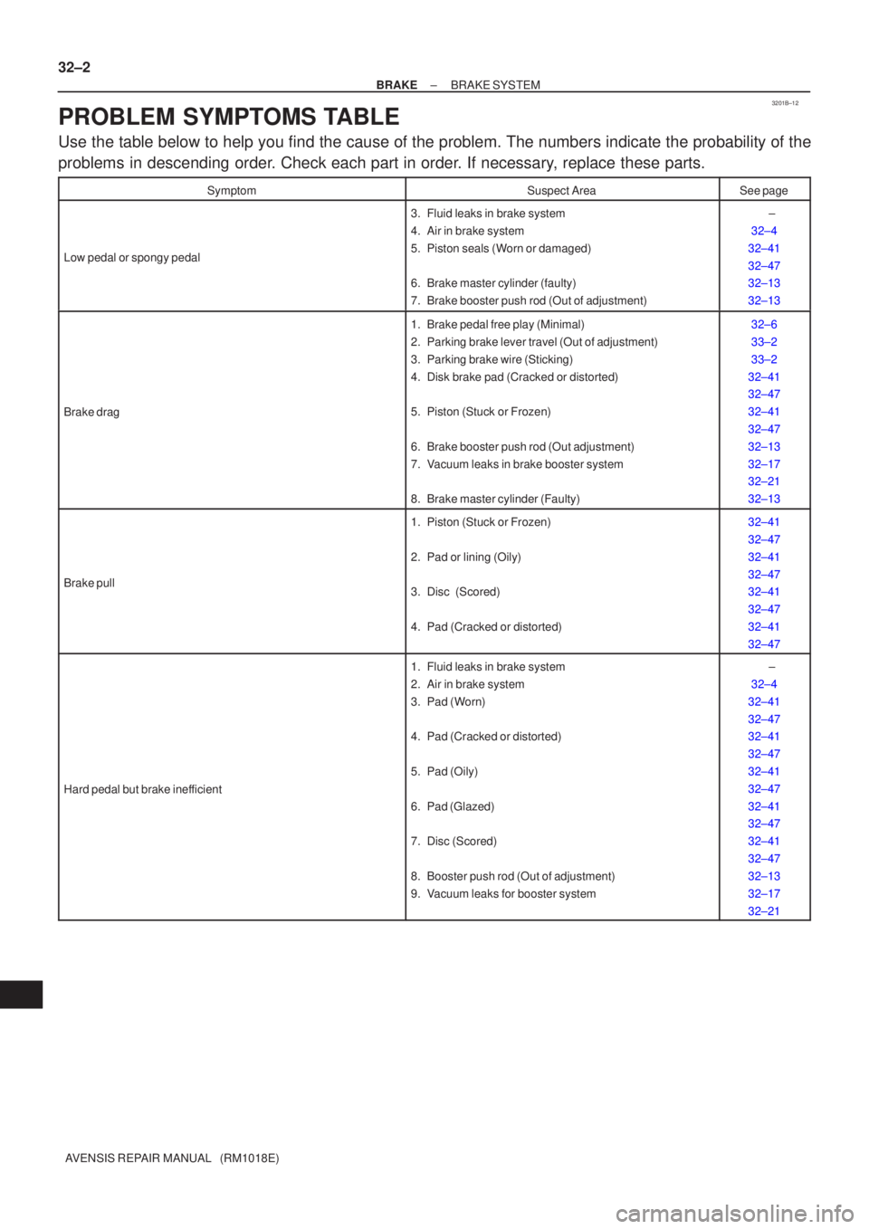
PROBLEM SYMPTOMS TABLE
Use the table below to help you find the cause of the problem. The numbers \
indicate the probability of the
problems in descending order. Check each part in order. If necessary, replace these parts.
SymptomSuspect AreaSee page
Low pedal or spongy pedal
3. Fluid leaks in brake system
4. Air in brake system
5. Piston seals (Worn or damaged)
6. Brake master cylinder (faulty)
7. Brake booster push rod (Out of adjustment) ±
32±4
32±41
32±47
32±13
32±13
Brake drag
1. Brake pedal free play (Minimal)
2. Parking brake lever travel (Out of adjustment)
3. Parking brake wire (Sticking)
4. Disk brake pad (Cracked or distorted)
5. Piston (Stuck or Frozen)
6. Brake booster push rod (Out adjustment)
7. Vacuum leaks in brake booster system
8. Brake master cylinder (Faulty)32±6
33±2
33±2
32±41
32±47
32±41
32±47
32±13
32±17
32±21
32±13
Brake pull
1. Piston (Stuck or Frozen)
2. Pad or lining (Oily)
3. Disc (Scored)
4. Pad (Cracked or distorted) 32±41
32±47
32±41
32±47
32±41
32±47
32±41
32±47
Hard pedal but brake inefficient
1. Fluid leaks in brake system
2. Air in brake system
3. Pad (Worn)
4. Pad (Cracked or distorted)
5. Pad (Oily)
6. Pad (Glazed)
7. Disc (Scored)
8. Booster push rod (Out of adjustment)
9. Vacuum leaks for booster system ±
32±4
32±41
32±47
32±41
32±47
32±41
32±47
32±41
32±47
32±41
32±47
32±13
32±17
32±21
Page 2596 of 5135
±
BRAKE BRAKE SYSTEM
32±3
AVENSIS REPAIR MANUAL (RM1018E)
Noise from brakes
1. Pad (Cracked or distorted)
2. Installation bolt (Loose)
3. Disc (Scored)
4. Pad support plate (Loose)
5. Sliding pin (Worn)
6. Pad (dirty)
7. Pad(Glazed)32±41
32±47
32±41
32±47
32±41
32±47
32±41
32±47
32±41
32±47
32±41
32±47
32±41
32±47