Page 2581 of 5135
3201G±07
BR2238
GOOD NO GOOD
2nd3rd
1st
BR2237
G24221
Ventilation No Ventilation
± BRAKEBRAKE BOOSTER ASSY (LHD)
32±17
AVENSIS REPAIR MANUAL (RM1018E)
BRAKE BOOSTER ASSY (LHD)
ON±VEHICLE INSPECTION
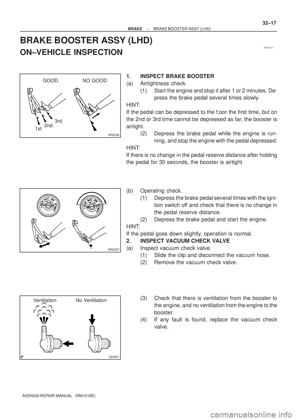
1. INSPECT BRAKE BOOSTER
(a) Airtightness check.
(1) Start the engine and stop it after 1 or 2 minutes. De-
press the brake pedal several times slowly.
HINT:
If the pedal can be depressed to the f;oor the first time, but on
the 2nd or 3rd time cannot be depreesed as far, the booster is
airtight.
(2) Depress the brake pedal while the engine is run-
ning, and stop the engine with the pedal depressed.
HINT:
If there is no change in the pedal reserve distance after holding
the pedal for 30 seconds, the booster is airtight.
(b) Operating check.
(1) Depress the brake pedal several times with the igni-
tion switch off and check that there is no change in
the pedal reserve distance.
(2) Depress the brake pedal and start the engine.
HINT:
If the pedal goes down slightly, operation is normal.
2. INSPECT VACUUM CHECK VALVE
(a) Inspect vacuum check valve.
(1) Slide the clip and disconnect the vacuum hose.
(2) Remove the vacuum check valve.
(3) Check that there is ventilation from the booster to
the engine, and no ventilation from the engine to the
booster.
(4) If any fault is found, replace the vacuum check
valve.
Page 2582 of 5135
320W6±01
G24218
G24217
F45393
± BRAKEBRAKE MASTER CYLINDER SUB±ASSY
32±13
AVENSIS REPAIR MANUAL (RM1018E)
REPLACEMENT
NOTICE:
Do not adjust the brake booster push rod.
1. DRAIN BRAKE FLUID
NOTICE:
Wash the brake fluid off immediately if it adheres to any painted surface.
2. REMOVE ENGINE ROOM RELAY BLOCK (LHD STEERING POSITION TYPE)
3. REMOVE AIR CLEANER CAP SUB±ASSY (LHD STEERING POSITION TYPE)
4. REMOVE CHARCOAL CANISTER ASSY (LHD STEERING POSITION TYPE)
5. REMOVE FUEL FILTER ASSY (LHD STEERING POSITION TYPE)
(a) Diesal engine type:
Remove the fuel filter assy with the 3 bolts.
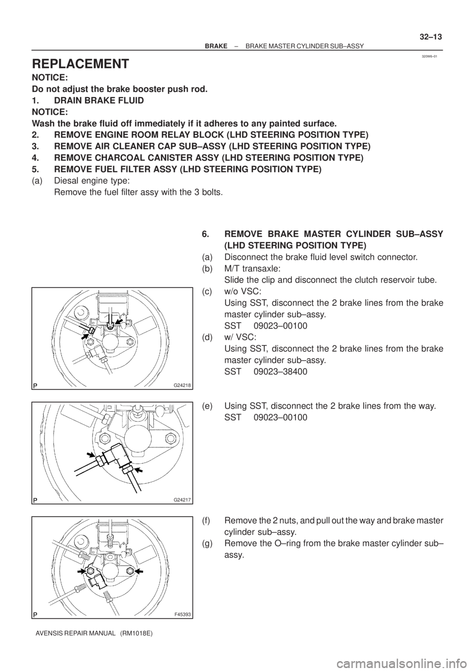
6. REMOVE BRAKE MASTER CYLINDER SUB±ASSY
(LHD STEERING POSITION TYPE)
(a) Disconnect the brake fluid level switch connector.
(b) M/T transaxle:
Slide the clip and disconnect the clutch reservoir tube.
(c) w/o VSC:
Using SST, disconnect the 2 brake lines from the brake
master cylinder sub±assy.
SST 09023±00100
(d) w/ VSC:
Using SST, disconnect the 2 brake lines from the brake
master cylinder sub±assy.
SST 09023±38400
(e) Using SST, disconnect the 2 brake lines from the way.
SST 09023±00100
(f) Remove the 2 nuts, and pull out the way and brake master
cylinder sub±assy.
(g) Remove the O±ring from the brake master cylinder sub±
assy.
Page 2583 of 5135
G24225
F45394
F45395Lithium soap base glycol grease
Grommets
Retainer
Washer
32±14
± BRAKEBRAKE MASTER CYLINDER SUB±ASSY
AVENSIS REPAIR MANUAL (RM1018E)
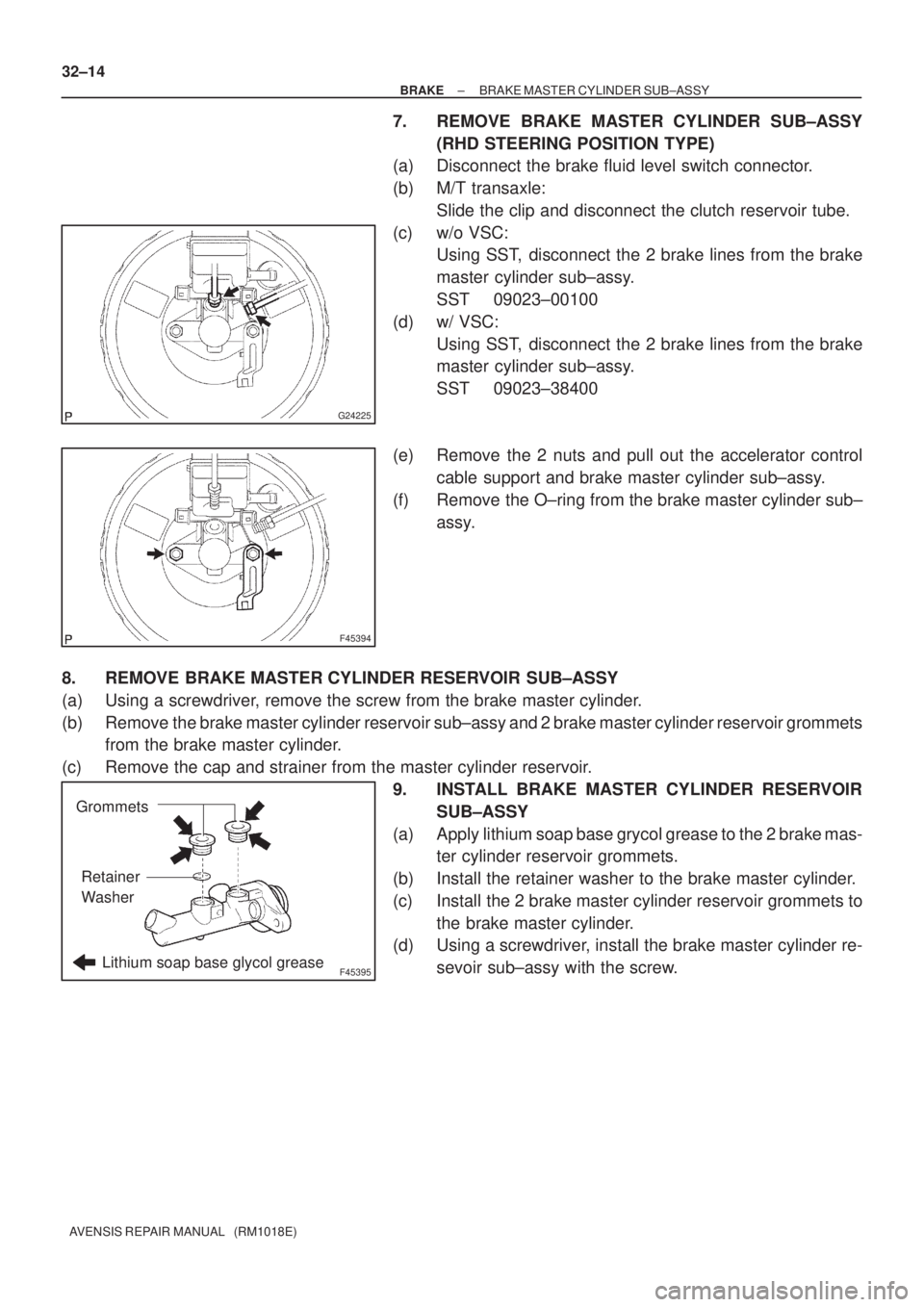
7. REMOVE BRAKE MASTER CYLINDER SUB±ASSY
(RHD STEERING POSITION TYPE)
(a) Disconnect the brake fluid level switch connector.
(b) M/T transaxle:
Slide the clip and disconnect the clutch reservoir tube.
(c) w/o VSC:
Using SST, disconnect the 2 brake lines from the brake
master cylinder sub±assy.
SST 09023±00100
(d) w/ VSC:
Using SST, disconnect the 2 brake lines from the brake
master cylinder sub±assy.
SST 09023±38400
(e) Remove the 2 nuts and pull out the accelerator control
cable support and brake master cylinder sub±assy.
(f) Remove the O±ring from the brake master cylinder sub±
assy.
8. REMOVE BRAKE MASTER CYLINDER RESERVOIR SUB±ASSY
(a) Using a screwdriver, remove the screw from the brake master cylinder.
(b) Remove the brake master cylinder reservoir sub±assy and 2 brake master cylinder reservoir grommets
from the brake master cylinder.
(c) Remove the cap and strainer from the master cylinder reservoir.
9. INSTALL BRAKE MASTER CYLINDER RESERVOIR
SUB±ASSY
(a) Apply lithium soap base grycol grease to the 2 brake mas-
ter cylinder reservoir grommets.
(b) Install the retainer washer to the brake master cylinder.
(c) Install the 2 brake master cylinder reservoir grommets to
the brake master cylinder.
(d) Using a screwdriver, install the brake master cylinder re-
sevoir sub±assy with the screw.
Page 2584 of 5135
F45393
G24217
G24218
F45394
± BRAKEBRAKE MASTER CYLINDER SUB±ASSY
32±15
AVENSIS REPAIR MANUAL (RM1018E)
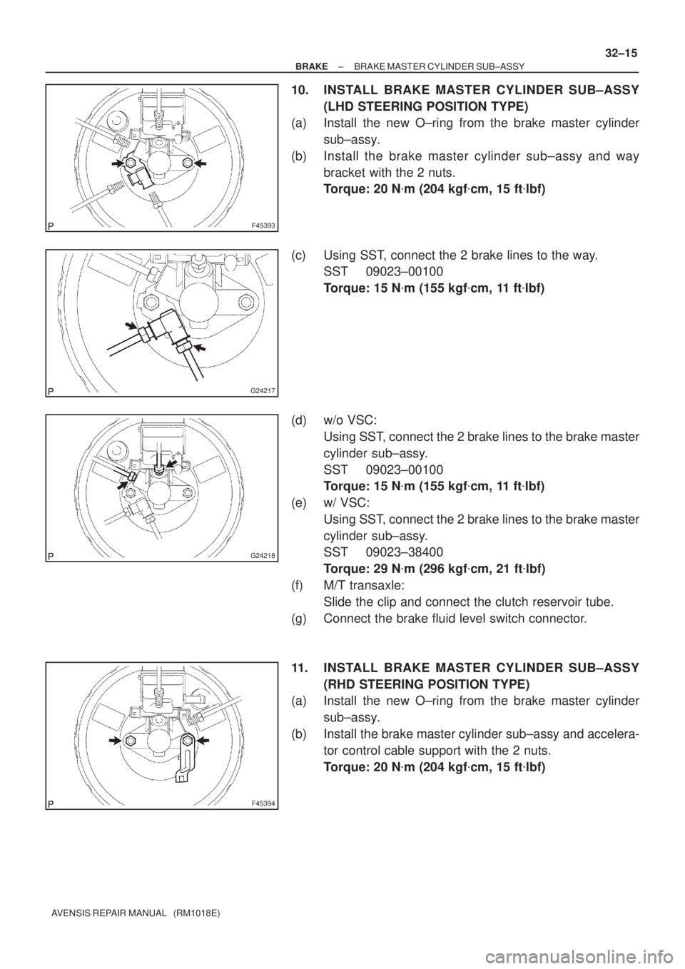
10. INSTALL BRAKE MASTER CYLINDER SUB±ASSY
(LHD STEERING POSITION TYPE)
(a) Install the new O±ring from the brake master cylinder
sub±assy.
(b) Install the brake master cylinder sub±assy and way
bracket with the 2 nuts.
Torque: 20 N�m (204 kgf�cm, 15 ft�lbf)
(c) Using SST, connect the 2 brake lines to the way.
SST 09023±00100
Torque: 15 N�m (155 kgf�cm, 11 ft�lbf)
(d) w/o VSC:
Using SST, connect the 2 brake lines to the brake master
cylinder sub±assy.
SST 09023±00100
Torque: 15 N�m (155 kgf�cm, 11 ft�lbf)
(e) w/ VSC:
Using SST, connect the 2 brake lines to the brake master
cylinder sub±assy.
SST 09023±38400
Torque: 29 N�m (296 kgf�cm, 21 ft�lbf)
(f) M/T transaxle:
Slide the clip and connect the clutch reservoir tube.
(g) Connect the brake fluid level switch connector.
11. INSTALL BRAKE MASTER CYLINDER SUB±ASSY
(RHD STEERING POSITION TYPE)
(a) Install the new O±ring from the brake master cylinder
sub±assy.
(b) Install the brake master cylinder sub±assy and accelera-
tor control cable support with the 2 nuts.
Torque: 20 N�m (204 kgf�cm, 15 ft�lbf)
Page 2585 of 5135
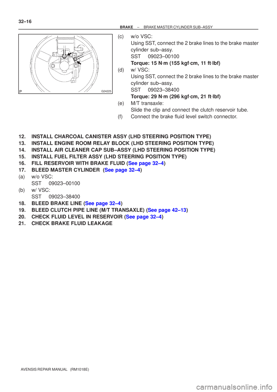
G24225
32±16
±
BRAKE BRAKE MASTER CYLINDER SUB±ASSY
AVENSIS REPAIR MANUAL (RM1018E)
(c) w/o VSC: Using SST, connect the 2 brake lines to the brake master
cylinder sub±assy.
SST 09023±00100
Torque: 15 N �m (155 kgf �cm, 11 ft �lbf)
(d) w/ VSC: Using SST, connect the 2 brake lines to the brake master
cylinder sub±assy.
SST 09023±38400
Torque: 29 N �m (296 kgf �cm, 21 ft �lbf)
(e) M/T transaxle: Slide the clip and connect the clutch reservoir tube.
(f) Connect the brake fluid level switch connector.
12. INSTALL CHARCOAL CANISTER ASSY (LHD STEERING POSITION TYPE)
13. INSTALL ENGINE ROOM RELAY BLOCK (LHD STEERING POSITION TYPE)
14. INSTALL AIR CLEANER CAP SUB±ASSY (LHD STEERING POSITION TYPE)
15. INSTALL FUEL FILTER ASSY (LHD STEERING POSITION TYPE)
16.FILL RESERVOIR WITH BRAKE FLUID (See page 32±4)
17.BLEED MASTER CYLINDER (See page 32±4)
(a) w/o VSC: SST 09023±00100
(b) w/ VSC: SST 09023±38400
18.BLEED BRAKE LINE (See page 32±4)
19.BLEED CLUTCH PIPE LINE (M/T TRANSAXLE) (See page 42±13)
20.CHECK FLUID LEVEL IN RESERVOIR (See page 32±4)
21. CHECK BRAKE FLUID LEAKAGE
Page 2586 of 5135
320W5±01
G24285
LHD Steering Position Type:
Charcoal Canister Assy
Brake Fluid Level
Switch Connector
Clutch Reservoir
Tube M/T Transaxle:Brake Booster Assy
Clip
Way
20 (204, 15)
15 (155, 11)
15 (155, 11)*1
29 (296, 21)*2
15 (155, 11)*1
29 (296, 21)*2
Brake Master
Cylinder Sub±assy
20 (204, 15)
Engin Room Relay Block
RHD Steering Position Type:Air Cleaner Cap Sub±assy
Brake Fluid Level
Switch ConnectorBrake Master
Cylinder Sub±assy
Clip
Accelerator Control
Cable Support
20 (204, 15)
*1
w/ ABS:*2 w/ VSC:N�m (kgf�cm, ft�lbf) : Specified torque
15 (155, 11)*1
29 (296, 21)*2
15 (155, 11)*1
29 (296, 21)*2
Clutch Reservoir
Tube M/T Transaxle:
Brake Booster Assy
5.4 (55, 48 in.�lbf)
Fuel Filter Assy Diesel Engin Type:
± BRAKEBRAKE MASTER CYLINDER SUB±ASSY
32±11
AVENSIS REPAIR MANUAL (RM1018E)
BRAKE MASTER CYLINDER SUB±ASSY
COMPONENTS
Page 2587 of 5135
G24284
Cap
Strainer
Brake Master Cylinder Reservoir Sub±Assy
Brake Master Cylinder
Reservoir Grommet
Brake Master Cylinder
Straight Pin
Screw
Lithium soap base glycol grease � Non±reusable part
N�m (kgf�cm, ft�lbf) : Specified torque
Brake Master Cylinder
Reservoir Grommet LHD Steering Position TypeRHD Steering Position Type
� O±Ring
Retianer Washer
32±12
± BRAKEBRAKE MASTER CYLINDER SUB±ASSY
AVENSIS REPAIR MANUAL (RM1018E)
Page 2588 of 5135
320VT±01
G23220
G23175
F43108
Stop Lamp Switch Assy
Cushion
1.5 ± 2.5 mm (0.059 ± 0.098 in.)
±
BRAKE BRAKE PEDAL SUB±ASSY
32±9
AVENSIS REPAIR MANUAL (RM1018E)
REPLACEMENT
1.REMOVE COMBINATION METER ASSEMBLY (See page 71±21)
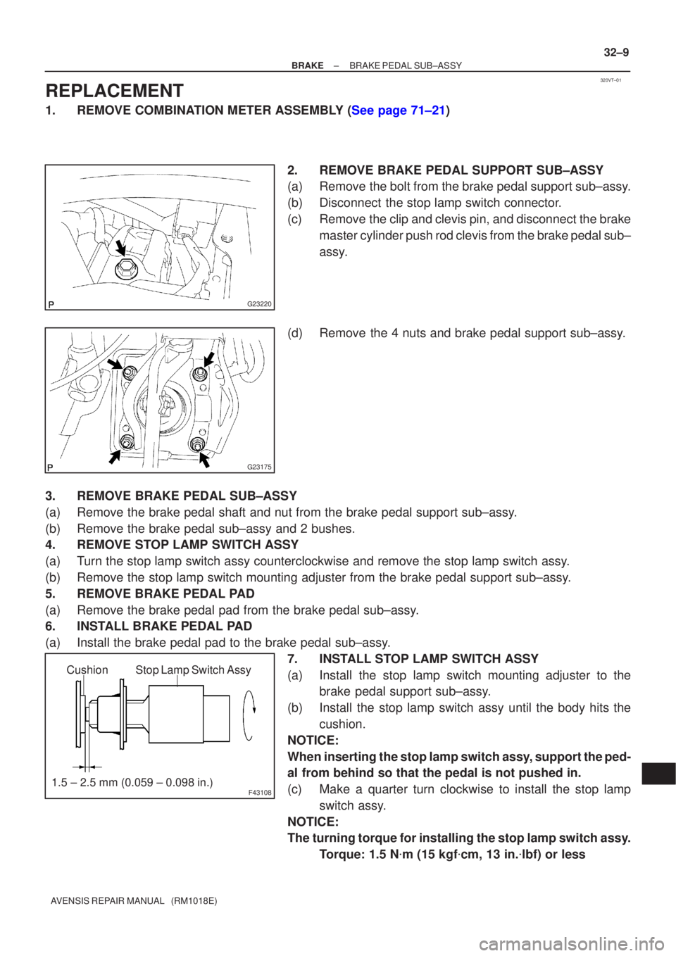
2. REMOVE BRAKE PEDAL SUPPORT SUB±ASSY
(a) Remove the bolt from the brake pedal support sub±assy.
(b) Disconnect the stop lamp switch connector.
(c) Remove the clip and clevis pin, and disconnect the brakemaster cylinder push rod clevis from the brake pedal sub±
assy.
(d) Remove the 4 nuts and brake pedal support sub±assy.
3. REMOVE BRAKE PEDAL SUB±ASSY
(a) Remove the brake pedal shaft and nut from the brake pedal support sub±\
assy.
(b) Remove the brake pedal sub±assy and 2 bushes.
4. REMOVE STOP LAMP SWITCH ASSY
(a) Turn the stop lamp switch assy counterclockwise and remove the stop lamp \
switch assy.
(b) Remove the stop lamp switch mounting adjuster from the brake pedal suppo\
rt sub±assy.
5. REMOVE BRAKE PEDAL PAD
(a) Remove the brake pedal pad from the brake pedal sub±assy.
6. INSTALL BRAKE PEDAL PAD
(a) Install the brake pedal pad to the brake pedal sub±assy. 7. INSTALL STOP LAMP SWITCH ASSY
(a) Install the stop lamp switch mounting adjuster to thebrake pedal support sub±assy.
(b) Install the stop lamp switch assy until the body hits the cushion.
NOTICE:
When inserting the stop lamp switch assy, support the ped-
al from behind so that the pedal is not pushed in.
(c) Make a quarter turn clockwise to install the stop lamp switch assy.
NOTICE:
The turning torque for installing the stop lamp switch assy. Torque: 1.5 N �m (15 kgf �cm, 13 in. �lbf) or less