Page 2910 of 5135
E65563
I22117
Condition
: Air conditioning system periodically repeats proper and improper function.
± HEATER & AIR CONDITIONERREFRIGERANT
55±33
AVENSIS REPAIR MANUAL (RM1018E)
(1) When the refrigerant volume is proper:
Gauge reading:
Low pressure side:
0.28 ± 0.4 MPa (2.8 ± 4.0 kgf/cm
2)
High pressure side:
1.3 ± 1.6 MPa (13 ± 16 kgf/cm
2)
(2) When there is moisture in the refrigeration system:
SymptomProbable causeDiagnosisRemedy
During operation, pressure on low
pressure side cycles between nor-
mal and vacuum
Moisture in refrigeration system
freezes at refrigerant filter orifice,
causing a temporary stop of cycle.
However, when it melts, normal
state is restored� Drier is overly saturated
� Moisture in refrigeration system
freezes at refrigerant filter orifice
and blocks circulation of refriger-
ant(1) Replace cooler drier
(2) Remove moisture in cycle by
repeatedly vacuuming
(3) Supply proper amount of new
refrigerant
Page 2911 of 5135

I22118
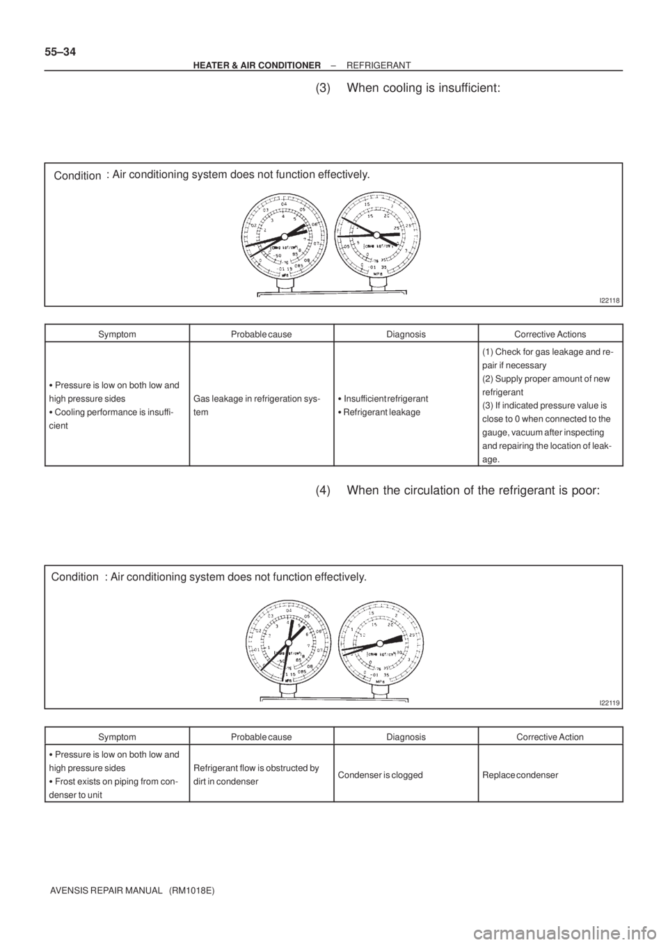
Condition: Air conditioning system does not function effectively.
I22119
Condition : Air conditioning system does not function effectively. 55±34
± HEATER & AIR CONDITIONERREFRIGERANT
AVENSIS REPAIR MANUAL (RM1018E)
(3) When cooling is insufficient:
SymptomProbable causeDiagnosisCorrective Actions
� Pressure is low on both low and
high pressure sides
� Cooling performance is insuffi-
cient
Gas leakage in refrigeration sys-
tem� Insufficient refrigerant
� Refrigerant leakage
(1) Check for gas leakage and re-
pair if necessary
(2) Supply proper amount of new
refrigerant
(3) If indicated pressure value is
close to 0 when connected to the
gauge, vacuum after inspecting
and repairing the location of leak-
age.
(4) When the circulation of the refrigerant is poor:
SymptomProbable causeDiagnosisCorrective Action
� Pressure is low on both low and
high pressure sides
� Frost exists on piping from con-
denser to unit
Refrigerant flow is obstructed by
dirt in condenserCondenser is cloggedReplace condenser
Page 2912 of 5135

I22120
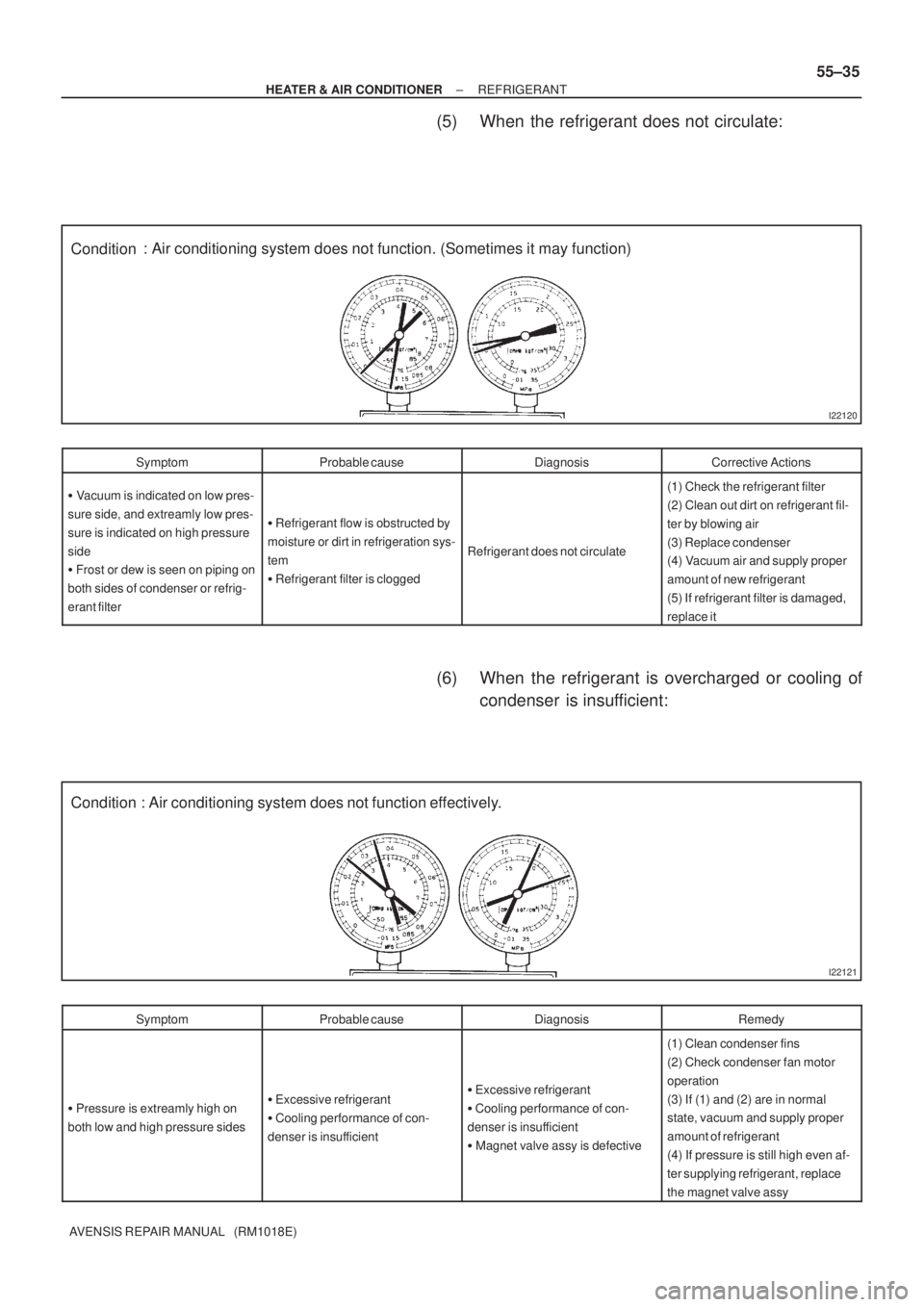
Condition: Air conditioning system does not function. (Sometimes it may function)
I22121
Condition : Air conditioning system does not function effectively.
± HEATER & AIR CONDITIONERREFRIGERANT
55±35
AVENSIS REPAIR MANUAL (RM1018E)
(5) When the refrigerant does not circulate:
SymptomProbable causeDiagnosisCorrective Actions
� Vacuum is indicated on low pres-
sure side, and extreamly low pres-
sure is indicated on high pressure
side
� Frost or dew is seen on piping on
both sides of condenser or refrig-
erant filter
� Refrigerant flow is obstructed by
moisture or dirt in refrigeration sys-
tem
� Refrigerant filter is clogged
Refrigerant does not circulate
(1) Check the refrigerant filter
(2) Clean out dirt on refrigerant fil-
ter by blowing air
(3) Replace condenser
(4) Vacuum air and supply proper
amount of new refrigerant
(5) If refrigerant filter is damaged,
replace it
(6) When the refrigerant is overcharged or cooling of
condenser is insufficient:
SymptomProbable causeDiagnosisRemedy
� Pressure is extreamly high on
both low and high pressure sides� Excessive refrigerant
� Cooling performance of con-
denser is insufficient� Excessive refrigerant
� Cooling performance of con-
denser is insufficient
� Magnet valve assy is defective
(1) Clean condenser fins
(2) Check condenser fan motor
operation
(3) If (1) and (2) are in normal
state, vacuum and supply proper
amount of refrigerant
(4) If pressure is still high even af-
ter supplying refrigerant, replace
the magnet valve assy
Page 2913 of 5135
I22122
Condition
NOTE : These gauge indica-
tions occur when the refrigera-
tion system opens and the re-
frigerant is charged without
vacuuming. : Air conditioning system does not function.
I22123
Condition : Air conditioning system does not function effectively. 55±36
± HEATER & AIR CONDITIONERREFRIGERANT
AVENSIS REPAIR MANUAL (RM1018E)
(7) When there is air in the refrigeration system:
SymptomProbable causeDiagnosisCorrective Actions
Pressure is extreamly high on both
low and the high pressure sidesAir in refrigeration system
� There is air in refrigeration sys-
tem
� Vacuuming is insufficient(1) Check if compressor oil is dirty
or insufficient
(2) Vacuum air and supply new re-
frigerant
(8) When the refrigerant filter is defective:
SymptomProbable causeDiagnosisCorrective Actions
� Pressure is extreamly high on
low pressure side
� Pressure is extreamly high on
high pressure side
Trouble with refrigerant filterExcessive refrigerantReplace refrigerant filter
Page 2914 of 5135
I22124
Condition : Air conditioning system does not function.
I22123
Condition: Air conditioning system does not function effectively.
± HEATER & AIR CONDITIONERREFRIGERANT
55±37
AVENSIS REPAIR MANUAL (RM1018E)
(9) When the compressor is defective:
SymptomProbable causeDiagnosisCorrective Actions
� Pressure is extreamly high on
low pressure side
� Pressure is extreamly low on
high pressure side
Internal leak from compressor
� Compression failure
� Leakage from damaged valve or
broken sliding parts
Replace or replace compressor
(10) When the magnet valve assy is defective:
SymptomProbable causeDiagnosisCorrective Actions
� Pressure is extreamly high on
low pressure sideInternal leak from magnet valve
assyMagnet valve assy failureReplace magnet valve assy
Page 2916 of 5135

550ZI±01
I35437
Connector ºBº Wire harness side:
Connector ºAº
I36091
Connector ºBº From back side:
Connector ºAº 55±22
± HEATER & AIR CONDITIONERHOT GAS TYPE POWER HEATER SYSTEM
AVENSIS REPAIR MANUAL (RM1018E)
HOT GAS TYPE POWER HEATER SYSTEM
ON±VEHICLE INSPECTION
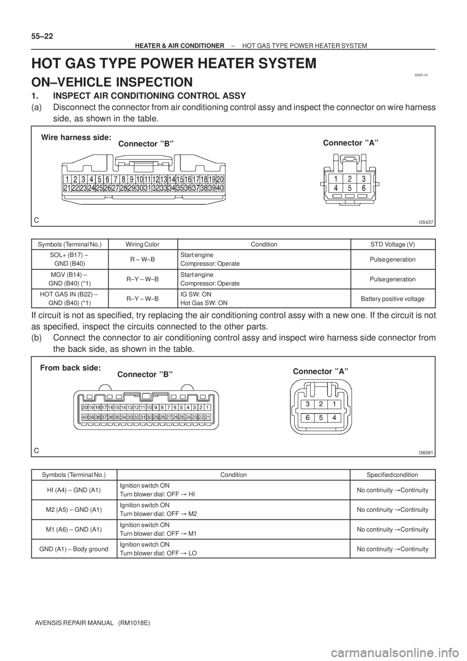
1. INSPECT AIR CONDITIONING CONTROL ASSY
(a) Disconnect the connector from air conditioning control assy and inspect the connector on wire harness
side, as shown in the table.
Symbols (Terminal No.)Wiring ColorConditionSTD Voltage (V)
SOL+ (B17) ±
GND (B40)R ± W±BStart engine
Compressor: OperatePulse generation
MGV (B14) ±
GND (B40) (*1)R±Y ± W±BStart engine
Compressor: OperatePulse generation
HOT GAS IN (B22) ±
GND (B40) (*1)R±Y ± W±BIG SW: ON
Hot Gas SW: ONBattery positive voltage
If circuit is not as specified, try replacing the air conditioning control assy with a new one. If the circuit is not
as specified, inspect the circuits connected to the other parts.
(b) Connect the connector to air conditioning control assy and inspect wire harness side connector from
the back side, as shown in the table.
Symbols (Terminal No.)ConditionSpecified condition
HI (A4) ± GND (A1)Ignition switch ON
Turn blower dial: OFF � HINo continuity �Continuity
M2 (A5) ± GND (A1)Ignition switch ON
Turn blower dial: OFF � M2No continuity �Continuity
M1 (A6) ± GND (A1)Ignition switch ON
Turn blower dial: OFF � M1No continuity �Continuity
GND (A1) ± Body groundIgnition switch ON
Turn blower dial: OFF � LONo continuity �Continuity
Page 2926 of 5135
550ZD±01
������E61224
E32877
± HEATER & AIR CONDITIONERAIR CONDITIONING SYSTEM
55±7
AVENSIS REPAIR MANUAL (RM1018E)
INSPECTION
1. INSPECT COMPRESSOR (MANUAL AIR
CONDITIONING)
(a) Measure the resistance between terminals 1 and 2.
Resistance: 10 to 11 � at 25�C (77�F)
If the resistance is not as specified, replace the compressor
assy.
2. INSPECT BLOWER RESISTOR (MANUAL AIR
CONDITIONING)
(a) Measure resistance between terminals, as shown in the
table.
Tester connectionSpecified condition
1 ± 21.404 to 1.716 �
1 ± 30.504 to 0.616 �
1 ± 43.024 to 3.696 �
If resistance is not as specified, replace the blower resistor.
Page 2927 of 5135
I36092
LHD Models:REC
FRS
I36094
I36093
RHD Models:
RECFRS
I36094
55±8
± HEATER & AIR CONDITIONERAIR CONDITIONING SYSTEM
AVENSIS REPAIR MANUAL (RM1018E)
3. INSPECT RECIRCULATION DAMPER SERVO
SUB±ASSY (MANUAL AIR CONDITIONING)
(a) Inspect servomotor operation.
(1) Connect the positive (+) lead from the battery to ter-
minal 3 and negative (±) lead to terminal 2, then
check that the arm turns to ºFRSº side smoothly.
(2) Connect the positive (+) lead from the battery to ter-
minal 3 and negative (±) lead to terminal 1, then
check that the arm turns to ºRECº side smoothly.
If operations are not as specified, replace the mode damper
servomotor.