Page 434 of 5135

05±302
± DIAGNOSTICSSFI SYSTEM (1AZ±FSE)
AVENSIS REPAIR MANUAL (RM1018E)Hand±held Tester DisplayDiagnostic Note Normal Condition *
1Measurement Item/Range
(Display)
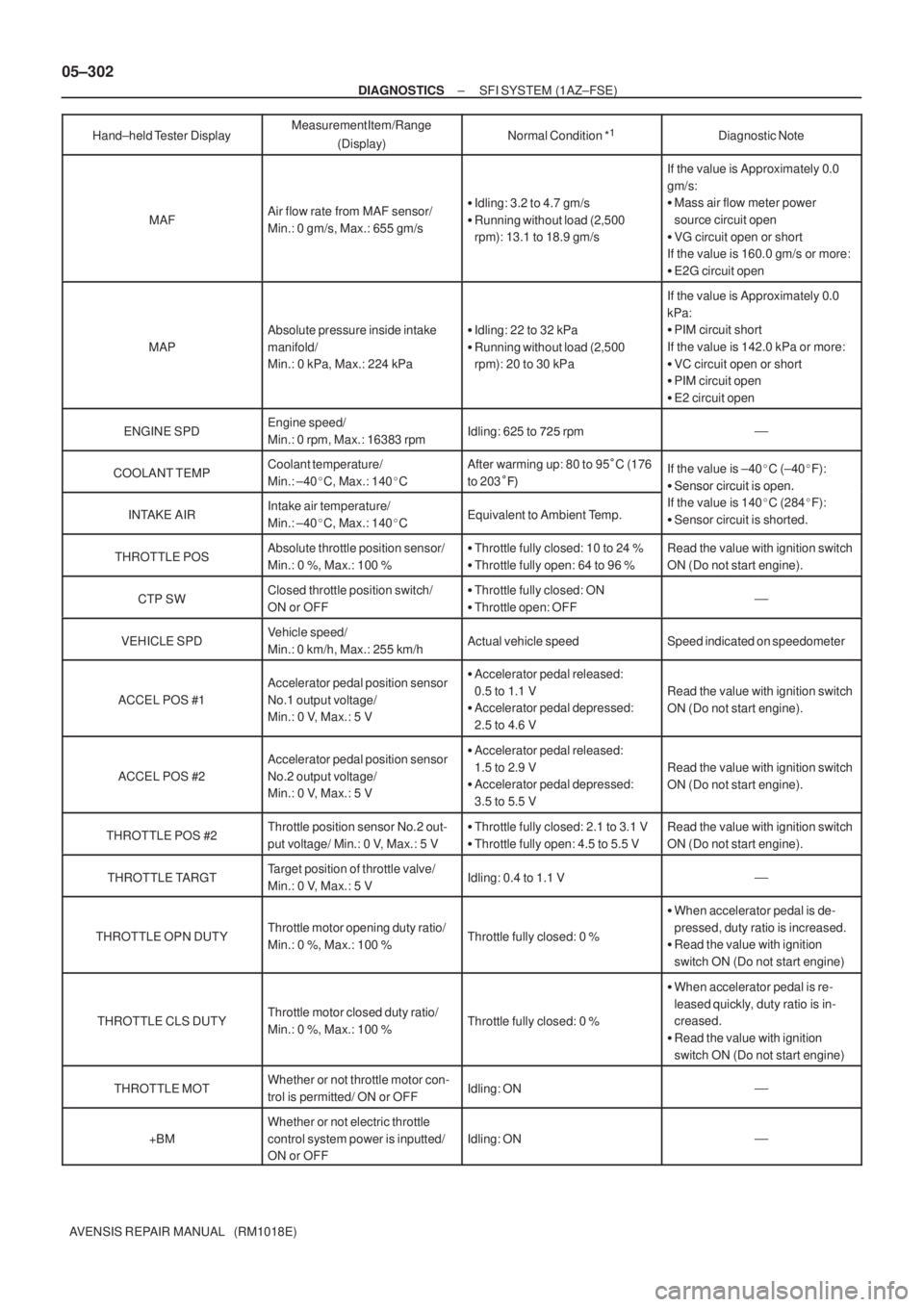
MAFAir flow rate from MAF sensor/
Min.: 0 gm/s, Max.: 655 gm/s�Idling: 3.2 to 4.7 gm/s
�Running without load (2,500
rpm): 13.1 to 18.9 gm/s
If the value is Approximately 0.0
gm/s:
�Mass air flow meter power
source circuit open
�VG circuit open or short
If the value is 160.0 gm/s or more:
�E2G circuit open
MAP
Absolute pressure inside intake
manifold/
Min.: 0 kPa, Max.: 224 kPa�Idling: 22 to 32 kPa
�Running without load (2,500
rpm): 20 to 30 kPa
If the value is Approximately 0.0
kPa:
�PIM circuit short
If the value is 142.0 kPa or more:
�VC circuit open or short
�PIM circuit open
�E2 circuit open
ENGINE SPDEngine speed/
Min.: 0 rpm, Max.: 16383 rpmIdling: 625 to ��� rpm�
COOLANT TEMPCoolant temperature/
Min.: ±40�C, Max.: 140�CAfter warming up: 80 to 95�C (176
to 203���If the value is ±40�C (±40�F):
�Sensor circuit is open.
INTAKE AIRIntake air temperature/
Min.: ±40�C, Max.: 140�CEquivalent to Ambient Temp.
�Sensor circuit is oen.
If the value is 140�C (284�F):
�Sensor circuit is shorted.
THROTTLE POSAbsolute throttle position sensor/
Min.: 0 %, Max.: 100 %�Throttle fully closed: 10 to 24 %
�Throttle fully open: 64 to 96 %Read the value with ignition switch
ON (Do not start engine).
CTP SWClosed throttle position switch/
ON or OFF�Throttle fully closed: ON
�Throttle open: OFF�
VEHICLE SPDVehicle speed/
Min.: 0 km/h, Max.: 255 km/hActual vehicle speedSpeed indicated on speedometer
ACCEL POS #1
Accelerator pedal position sensor
No.1 output voltage/
Min.: 0 V, Max.: 5 V�Accelerator pedal released:
0.5 to 1.1 V
�Accelerator pedal depressed:
2.5 to 4.6 V
Read the value with ignition switch
ON (Do not start engine).
ACCEL POS #2
Accelerator pedal position sensor
No.2 output voltage/
Min.: 0 V, Max.: 5 V�Accelerator pedal released:
1.5 to 2.9 V
�Accelerator pedal depressed:
3.5 to 5.5 V
Read the value with ignition switch
ON (Do not start engine).
THROTTLE POS #2Throttle position sensor No.2 out-
put voltage/ Min.: 0 V, Max.: 5 V�Throttle fully closed: 2.1 to 3.1 V
�Throttle fully open: 4.5 to 5.5 VRead the value with ignition switch
ON (Do not start engine).
THROTTLE TARGTTarget position of throttle valve/
Min.: 0 V, Max.: 5 VIdling: 0.4 to 1.1 V�
THROTTLE OPN DUTYThrottle motor opening duty ratio/
Min.: 0 %, Max.: 100 %Throttle fully closed: 0 %
�When accelerator pedal is de-
pressed, duty ratio is increased.
�Read the value with ignition
switch ON (Do not start engine)
THROTTLE CLS DUTYThrottle motor closed duty ratio/
Min.: 0 %, Max.: 100 %Throttle fully closed: 0 %
�When accelerator pedal is re-
leased quickly, duty ratio is in-
creased.
�Read the value with ignition
switch ON (Do not start engine)
THROTTLE MOTWhether or not throttle motor con-
trol is permitted/ ON or OFFIdling: ON�
+BM
Whether or not electric throttle
control system power is inputted/
ON or OFF
Idling: ON�
Page 439 of 5135

A59673
Inside
±
DIAGNOSTICS SFI SYSTEM(1AZ±FSE)
05±307
AVENSIS REPAIR MANUAL (RM1018E)
BASIC INSPECTION
When the malfunction code is not confirmed in the DTC check, troubleshooting should be carried out in all
the possible circuits considered as causes of the problems. In many cases, by carrying out the basic engi\
ne
check shown in the following flow chart, the location causing the problem can be found quickly and efficiently.
Therefore, using this check is essential in the engine troubleshooting.
1CHECK BATTERY VOLTAGE
NOTICE:
Carry out this check with the engine stopped and ignition switch OFF.
OKNG
Voltage11 V or moreLess than 11 V
NGCHARGE OR REPLACE BATTERY
OK
2CHECK IF ENGINE WILL CRANK
NGPROCEED TO PROBLEM SYMPTOMS TABLE ON PAGE 05±320
OK
3CHECK IF ENGINE STARTS
NGGO TO STEP 7
OK
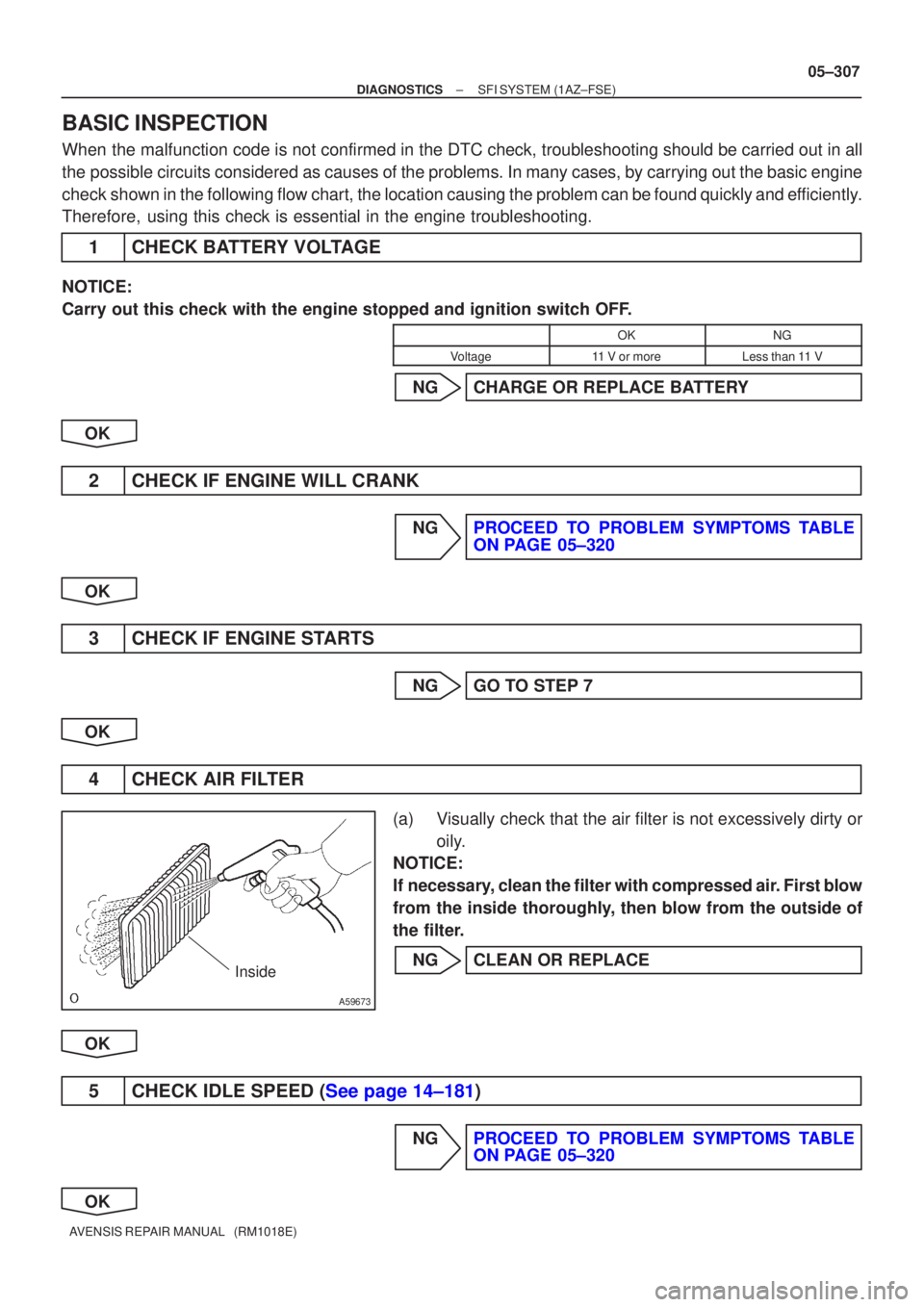
4CHECK AIR FILTER
(a)Visually check that the air filter is not excessively dirty or oily.
NOTICE:
If necessary, clean the filter with compressed air. First blow
from the inside thoroughly, then blow from the outside of
the filter.
NGCLEAN OR REPLACE
OK
5CHECK IDLE SPEED (See page 14±181)
NGPROCEED TO PROBLEM SYMPTOMS TABLE ON PAGE 05±320
OK
Page 443 of 5135
±
DIAGNOSTICS SFI SYSTEM(1AZ±FSE)
05±291
AVENSIS REPAIR MANUAL (RM1018E)
9SYMPTOM SIMULATION
10DTC CHECK (See page 05±294)
AMalfunction code
BNo code
B GO TO STEP 12
A
11DTC CHART (See page 05±309)
GO TO STEP 14
12BASIC INSPECTION (See page 05±294)
AWrong parts not confirmed
BWrong parts confirmed
B GO TO STEP 17
A
13PROBLEM SYMPTOMS TABLE (See page 05±320)
AWrong circuit confirmed
BWrong parts confirmed
B GO TO STEP 17
A
14CHECK ECM POWER SOURCE CIRCUIT (See page 05±502)
15 CIRCUIT INSPECTION
AMalfunction not confirmed
BMalfunction confirmed
B GO TO STEP 18
A
Page 445 of 5135
A76892
V3
Variable Resister
VCC 2
VA F 3
E2
1R±W
P
BR10
EA13
EA19
EA1ECM
5V
VC
VA F
E1
E2 R±W
P
BRE1318
32
E13
28
E13 05±286
± DIAGNOSTICSSFI SYSTEM (1AZ±FE)
AVENSIS REPAIR MANUAL (RM1018E)
VARIABLE RESISTOR CIRCUIT
CIRCUIT DESCRIPTION
The variable resister has been adopted to leaded±type vehicle only.
This resistor is used change the air±fuel ratio of the air±fuel mixture.
The idle mixture is adjusted using this resistor.
Turning the idle mixture adjusting screw clockwise moves the contacts inside the resistor, raising the terminal
VAF voltage. Conversely, turning the screw counterclockwise lowers the terminal VAF voltage.
When the terminal VAF voltage rises, the ECM increases the injection volume slightly, marking the air±fuel
mixture a little richer.
WIRING DIAGRAM
INSPECTION PROCEDURE
NOTICE:
Always use a CO meter when adjusting the idle mixture. If a CO meter is not available, DO NOT AT-
TEMPT TO ADJUST IDLE MIXTURE.
05C7E±01
Page 449 of 5135

A76890
4 D5
DLC3
CGTC13
W±BCBW±L20
E9TCECM
W±L
W±B J8
J/C
BB
J16
J/C A
IP IOCenter J/B
CA 36
A(RHD) W±B
(RHD)
(LHD)W±B
(LHD) (LHD)W±L
(LHD)
W±L
(RHD)DB
DC 17 3Driver Side J/B
3 2 1 45678
9 1 0 111 21 31 41 51 6
DLC3
A04550
CG (±)TC (+)
DLC3
05±284
± DIAGNOSTICSSFI SYSTEM (1AZ±FE)
AVENSIS REPAIR MANUAL (RM1018E)
TC TERMINAL CIRCUIT
CIRCUIT DESCRIPTION
Terminals TC and CG are located in the DLC3. When connecting these terminals, DTCs in normal mode or
check mode can be read through the CHK ENG flashing in the combination meter.
WIRING DIAGRAM
INSPECTION PROCEDURE
HINT:
�Even though terminal TC is not connected to terminal CG, the CHK ENG blinks.
�For the above phenomenon, an open or short in the wire harness, or malfunction inside the ECM is
the likely cause.
1 CHECK DLC3(TC VOLTAGE)
(a) Turn the ignition switch ON.
(b) Measure the voltage between the terminals of the DLC3.
Standard:
Symbols (Terminal No.)Specified condition
TC (13) ± CG (4)9 to 14 V
OK Go to step 3
NG
05C7D±01
Page 451 of 5135
A81015
Engine
Room
R/B No. 1
Engine
Room
J/B No. 1W
9ECM
W
E9 11
1 2
B±W22 1
4A
Battery4
2I13
Ignition
Switch
DH 6
B±R B±R
C11
Combination
Meter Assy
Check
Engine
Warning
Light AM2
IG2
AM2
Driver
Side
J/B
FL MAINEngine
Room
J/B
No. 4
4BB±G 1A 1B±R
IE41
(LHD)IP11
(RHD)
18 DA
J8C
(LHD)J26A
(RHD)J8C
(LHD)J26A
(RHD) J/CB±W IGN
1
1
B±G 05±282
± DIAGNOSTICSSFI SYSTEM (1AZ±FE)
AVENSIS REPAIR MANUAL (RM1018E)
CHECK ENGINE WARNING LIGHT CIRCUIT
CIRCUIT DESCRIPTION
If the ECM detects a trouble, the CHK ENG is illuminated. At this time, the ECM records a DTC in the memory.
WIRING DIAGRAM
INSPECTION PROCEDURE
HINT:
Troubleshoot each trouble symptom in accordance with the chart below .
CHK ENG remains onStart inspection from step 1
CHK ENG is not illuminateStart inspection from step 3
05C7C±01
Page 452 of 5135

A65748
E9
ECM Connector
±
DIAGNOSTICS SFI SYSTEM(1AZ±FE)
05±283
AVENSIS REPAIR MANUAL (RM1018E)
1CLEAR DTC
(a)Connect the hand±held tester to the DLC 3.
(b)Turn the ignition switch ON and push the hand±held tester main switch \
ON.
(c)Read the DTC (See page 05±149).
(d)Clear the DTC (See page 05±149).
(e)Check that the CHK ENG is OFF.
Standard: CHK ENG is OFF
OKREPAIR CIRCUIT INDICATED BY OUTPUTCODE (See page 05±161)
NG
2CHECK HARNESS AND CONNECTOR(CHECK FOR SHORT IN WIRE HARNESS)
(a)Disconnect the E9 ECM connector.
(b)Turn the ignition switch ON.
(c)Check that the CHK ENG is OFF. Standard: CHK ENG is OFF
OKCHECK AND REPLACE ECM (See page 01±32)
NG
CHECK AND REPAIR HARNESS AND CONNECTOR
3CHECK CHK ENG CONDITION
(a)Check that the CHK ENG is illuminated when turning the ignition switch O\
N. Standard: CHK ENG is illuminated
OKCHECK AND REPAIR HARNESS ANDCONNECTOR
NG
4INSPECT COMBINATION METER ASSY(CHK ENG CIRCUIT)
(a)See the combination meter troubleshooting on page 05±1509. NG REPAIR OR REPLACE BULB OR COMBINATIONMETER ASSEMBLYSYSTEM OK
OK
CHECK AND REPAIR HARNESS AND CONNECTOR
Page 453 of 5135
A76870
ECM
STA
E129
B±Y
IJW±BJ12
B B J13
J/C W±B 1 5
32 1AM2 2
B±G
B±R1
S51S4
Starter
Battery7
IK1
FL MAIN 4B 4A
Engine Room
J/B No. 4
BB 55
55 1
11A
B±GB±R
IE41
(LHD)IP11
(RHD)B±R
Engine
Room
R/B No. 1
Engine
Room
J/B No.1
Driver
Side R/BST
Relay
2DJ
9DA Driver
Side J/B B±R
B±RI13
Ignition Switch
45B±Y
B±Y
6
2ST 1
6 Fuse
Block
B±WB±YB±Y B±Y
J12 A C J13
A
J12 1
1
(M/T)
B±W
(A/T)
N1
Neutral Start SW96B±Y
(A/T) 05±278
± DIAGNOSTICSSFI SYSTEM (1AZ±FE)
AVENSIS REPAIR MANUAL (RM1018E)
STARTER SIGNAL CIRCUIT
CIRCUIT DESCRIPTION
When the engine is cranked, the intake air flow becomes slow, so fuel vaporization is poor. A rich mixture
is therefore necessary in order to achieve good startability. While the engine is being cranked, the battery
voltage is applied to terminal STA of the ECM. The starter signal is mainly used to increase the fuel injection
volume for the starting injection control and after±start injection control.
WIRING DIAGRAM
05C7B±01