Page 454 of 5135
±
DIAGNOSTICS SFI SYSTEM(1AZ±FE)
05±279
AVENSIS REPAIR MANUAL (RM1018E)
INSPECTION PROCEDURE
HINT:
This chart is on the premise that the engine is cranked normally. If the engine is not cranked, proceed to the
problem symptoms table on page 05±168.
When using hand±held tester:
1READ VALUE OF HAND±HELD TESTER(STA SIGNAL)
(a)Connect the hand±held tester to the DLC3.
(b)Turn the ignition switch ON and push the hand±held tester main switch \
ON.
(c)Select the item ºDIAGNOSIS / OBD/MOBD / DATA LIST / ALL / STARTER SIGº and read its value dis-
played on the hand±held tester.
Result:
Ignition Switch PositionONSTART
STA SignalOFFON
OKPROCEED TO NEXT CIRCUIT INSPECTION SHOWN ON PROBLEM SYMPTOMS TABLE
(See page 05±149)
NG
Page 456 of 5135
A65745
STA
E12
ECM Connector
A79097
Driver Side R/B
LHDStarter Relay
A79098
Driver Side R/B
RHD
Starter Relay
±
DIAGNOSTICS SFI SYSTEM(1AZ±FE)
05±281
AVENSIS REPAIR MANUAL (RM1018E)
(c)Measure the voltage between the terminals of the E12
ECM connector when the engine is cranked.
Standard:
Symbols (Terminal No.)Specified condition
STA (E12±9) ± E1 (E12±7)6 V or more
OKPROCEED TO NEXT CIRCUIT INSPECTION SHOWN ON PROBLEM SYMPTOMS TABLE
(See page 05±149)
NG
2CHECK HARNESS AND CONNECTOR
(a)Disconnect the E12 ECM connector.
(b)Remove the starter relay from the driver side R/B.
(c)Check for continuity between the wire harness side con- nectors.
Standard (Check for open):
Symbols (Terminal No.)Specified condition
Starter relay (1) ± STA (E12±9)Continuity
Standard (Check for short):
Symbols (Terminal No.)Specified condition
Starter relay (1) or STA (12±9) ± Body groundNo continuity
NGREPAIR OR REPLACE HARNESS OR CONNECTOR
OK
CHECK AND REPLACE ECM (See page 01±32)
Page 457 of 5135
A78423
20V
/Division Injector Signal Waveform
20V
/Division
GND
100 msec./Division (Idling)(Magnification)
GND
1 msec./Division (Idling)
Injection duration
05±272
± DIAGNOSTICSSFI SYSTEM (1AZ±FE)
AVENSIS REPAIR MANUAL (RM1018E)
FUEL INJECTOR CIRCUIT
CIRCUIT DESCRIPTION
The fuel injectors are located on the intake manifold.
They inject fuel into the cylinders based on the signals from the ECM.
Reference: Inspection using oscilloscope
With the engine idling, check the waveform between terminals #1 to #4 and E01 of the ECM connectors.
HINT:
The correct waveform is as shown in the diagram below.
05C7A±01
Page 461 of 5135
A66267
IG2 Wire Harness Side
Ignition Switch Connector
I13
A79103
Driver Side J/B
IGN Fuse12
������A79064
Engine Room R/B No.4
IG2 Relay
05±276
± DIAGNOSTICSSFI SYSTEM (1AZ±FE)
AVENSIS REPAIR MANUAL (RM1018E)
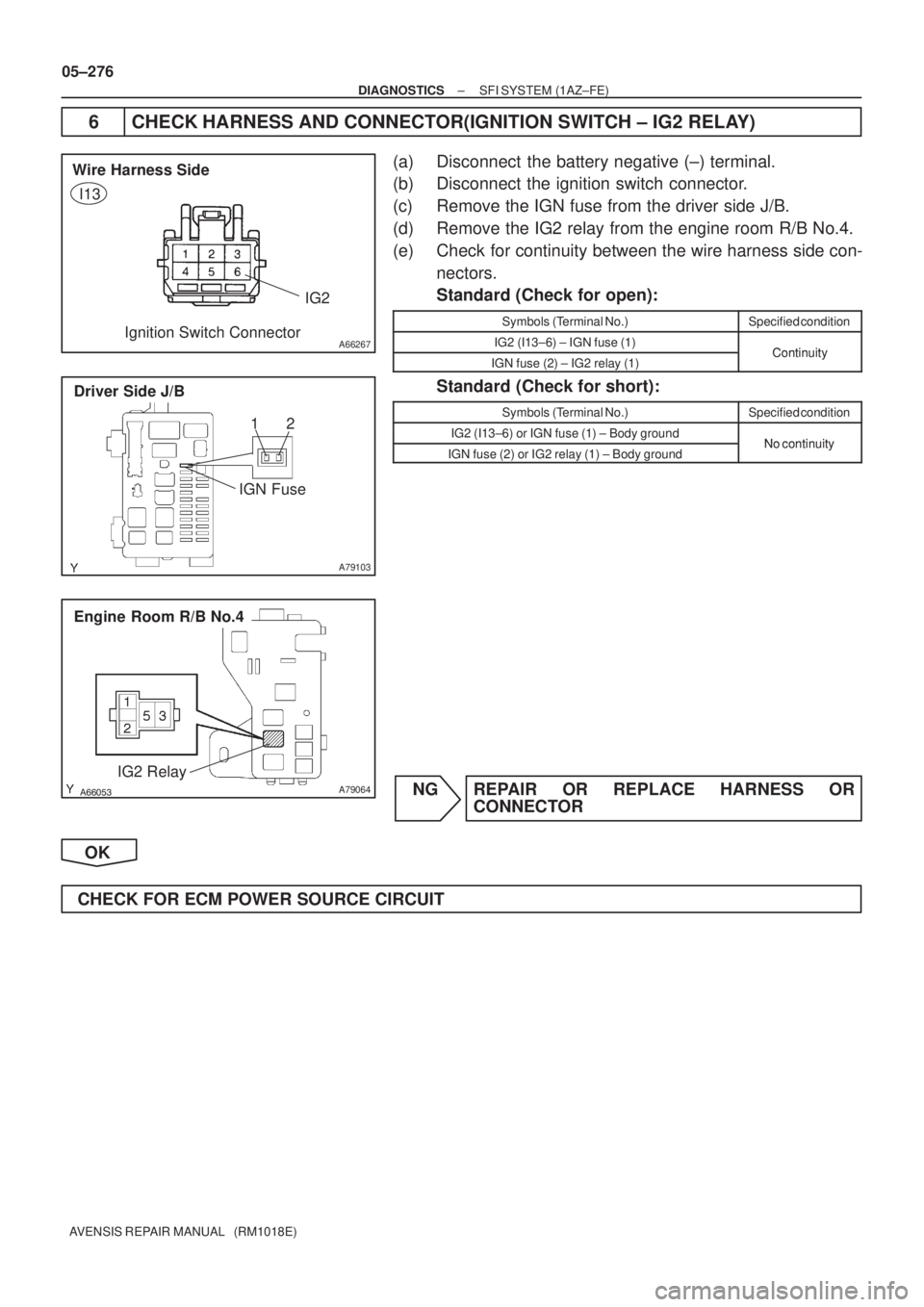
6 CHECK HARNESS AND CONNECTOR(IGNITION SWITCH ± IG2 RELAY)
(a) Disconnect the battery negative (±) terminal.
(b) Disconnect the ignition switch connector.
(c) Remove the IGN fuse from the driver side J/B.
(d) Remove the IG2 relay from the engine room R/B No.4.
(e) Check for continuity between the wire harness side con-
nectors.
Standard (Check for open):
Symbols (Terminal No.)Specified condition
IG2 (I13±6) ± IGN fuse (1)ContinuityIGN fuse (2) ± IG2 relay (1)Continuity
Standard (Check for short):
Symbols (Terminal No.)Specified condition
IG2 (I13±6) or IGN fuse (1) ± Body groundNo continuityIGN fuse (2) or IG2 relay (1) ± Body groundNo continuity
NG REPAIR OR REPLACE HARNESS OR
CONNECTOR
OK
CHECK FOR ECM POWER SOURCE CIRCUIT
Page 462 of 5135
A65743
E13
ECM ConnectorE02E01
±
DIAGNOSTICS SFI SYSTEM(1AZ±FE)
05±277
AVENSIS REPAIR MANUAL (RM1018E)
7INSPECT ECM
(a)Disconnect the ECM E13 connector.
(b)Check for continuity between the ECM connector and
body ground.
Standard (Check for open):
Symbols (Terminal No.)Specified condition
E01 (E13±7) ± Body groundContinuityE02 (E13±6) ± Body groundContinuity
NGREPAIR OR REPLACE HARNESS OR CONNECTOR
OK
8INSPECT FUEL INJECTOR ASSY(CHECK INJECTOR VOLUME) (See page 11±22)
NGREPLACE FUEL INJECTOR ASSY
OK
PROCEED TO NEXT CIRCUIT INSPECTION SHOWN ON PROBLEM SYMPTOMS TABLE
(See page 05±168)
Page 463 of 5135
05±362
±
DIAGNOSTICS SFI SYSTEM(1AZ±FSE)
AVENSIS REPAIR MANUAL (RM1018E)
DTCP0121THROTTLE/PEDAL POSITION SENSOR/SWITCH ºAº CIRCUIT
RANGE/PERFORMANCE PROBLEM
HINT:
This is the procedure of the ºthrottle position sensorº.
CIRCUIT DESCRIPTION
Refer to DTC P0120 on page 05±356.
DTC No.DTC Detection ConditionTrouble Area
P0121Condition (a) continues for 2.0 seconds:
(a) Difference between VTA1 and VTA2 is out of thresholdThrottle position sensor (built in throttle body)
INSPECTION PROCEDURE
HINT:
Read freeze frame data using the hand±held tester. Freeze frame data records the engine conditions when
a malfunction is detected. When troubleshooting, it is useful for determi\
ning whether the vehicle was running
or stopped, the engine was warmed up or not, the air±fuel ratio was lea\
n or rich, etc. at the time of the mal-
function.
REPLACE THROTTLE BODY ASSY
05CK8±01
Page 464 of 5135
05±356
± DIAGNOSTICSSFI SYSTEM (1AZ±FSE)
AVENSIS REPAIR MANUAL (RM1018E)
DTC P0120 THROTTLE/PEDAL POSITION
SENSOR/SWITCH ºAº CIRCUIT
DTC P0122 THROTTLE/PEDAL POSITION
SENSOR/SWITCH ºAº CIRCUIT LOW INPUT
DTC P0123 THROTTLE/PEDAL POSITION
SENSOR/SWITCH ºAº CIRCUIT HIGH INPUT
DTC P0220 THROTTLE/PEDAL POSITION
SENSOR/SWITCH ºBº CIRCUIT
DTC P0222 THROTTLE/PEDAL POSITION
SENSOR/SWITCH ºBº CIRCUIT LOW INPUT
DTC P0223 THROTTLE/PEDAL POSITION
SENSOR/SWITCH ºBº CIRCUIT HIGH INPUT
DTC P2135 THROTTLE/PEDAL POSITION
SENSOR/SWITCH ºAº/ºBº VOLTAGE
CORRELATION
HINT:
This is repair procedure of ºthrottle position sensorº.
05CK7±01
Page 465 of 5135

Fail Safe Angle
*1
Usable Range
Throttle Valve Opening Angle (deg)84")
������A19802
Throttle Position Sensor ECM
Magnet
Magnet
IC No.2 IC No.1
VC
VTA1
E2 VTA2Throttle Position Sensor Output Voltage (V)
Fail Safe Angle
*1
Usable Range
Throttle Valve Opening Angle (deg)84 6.5
0 5
2.58
2.25
0.95
0.69
Throttle Valve Fully Opened
(Throttle Position Opening Position Expressed as Percentage
(VTA1) 64 to 96 %)
Fail Safe Angle 6.5�
(Throttle Position Opening Position Expressed as Percentage
(VTA1) about 16 %) Throttle Valve Fully Closed
(Throttle Position Opening Position Expressed as Percentage
(VTA1) 10 to 24 %)
*1:
VTA1 VTA2
± DIAGNOSTICSSFI SYSTEM (1AZ±FSE)
05±357
AVENSIS REPAIR MANUAL (RM1018E)
CIRCUIT DESCRIPTION
HINT:
�This electrical throttle system is no used throttle cable.
�This throttle position sensor is non±contact type.
The throttle position sensor is mounted on the throttle body to detect the opening angle of the throttle valve.
Since this sensor is electronically controlled with hall elements, accurate control and reliability can be ob-
tained. It has 2 sensors to detect the throttle opening angle and a malfunction of the throttle position sensor.
The voltage is applied to the terminals VTA1 and VTA2 of the ECM changes between 0 V and 5 V in propor-
tion to the opening angle of the throttle valve. The VTA1 is a signal to indicate the actual throttle valve open-
ing angle which is used for the engine control, and the VTA2 is a signal to indicate the information about the
opening angle which is used for detecting a malfunction.
The ECM judges the current opening angle of the throttle valve from these signals input from terminals VTA1
and VTA2, and the ECM controls the throttle motor to make the throttle valve angle properly in response to
the driving condition.

05±279
AVENSIS REPAIR MANUAL (RM1018E)
INSPECTION PROCEDURE
HINT:
This chart is on the premise that the engine is cranked normally. If the engine is not cranked,")

05±281
AVENSIS REPAIR MANUAL (RM1018E)
(c)Measure th")
(Magnification)
GND
1 msec./Division (Idling)
Injection duration
05±272
± DIAGNOSTICSSFI SYSTEM (1AZ±FE)
A")

05±277
AVENSIS REPAIR MANUAL (RM1018E)
7INSPECT ECM
(a)Disconnect the ECM E13 connector.
(b)Check for continuity between the ECM co")

AVENSIS REPAIR MANUAL (RM1018E)
DTCP0121THROTTLE/PEDAL POSITION SENSOR/SWITCH ºAº CIRCUIT
RANGE/PERFORMANCE PROBLEM
HINT:
This is the procedure of the �")

AVENSIS REPAIR MANUAL (RM1018E)
DTC P0120 THROTTLE/PEDAL POSITION
SENSOR/SWITCH ºAº CIRCUIT
DTC P0122 THROTTLE/PEDAL POSITION
SENSOR/SWITCH ºAº CIRCUI")