Page 2542 of 5135
�����F40210SST
�����F40211
SST
C68341
�����F40212
SST
�����F40213
30±12
± DRIVE SHAFT / PROPELLER SHAFTFRONT DRIVE SHAFT
AVENSIS REPAIR MANUAL (RM1018E)
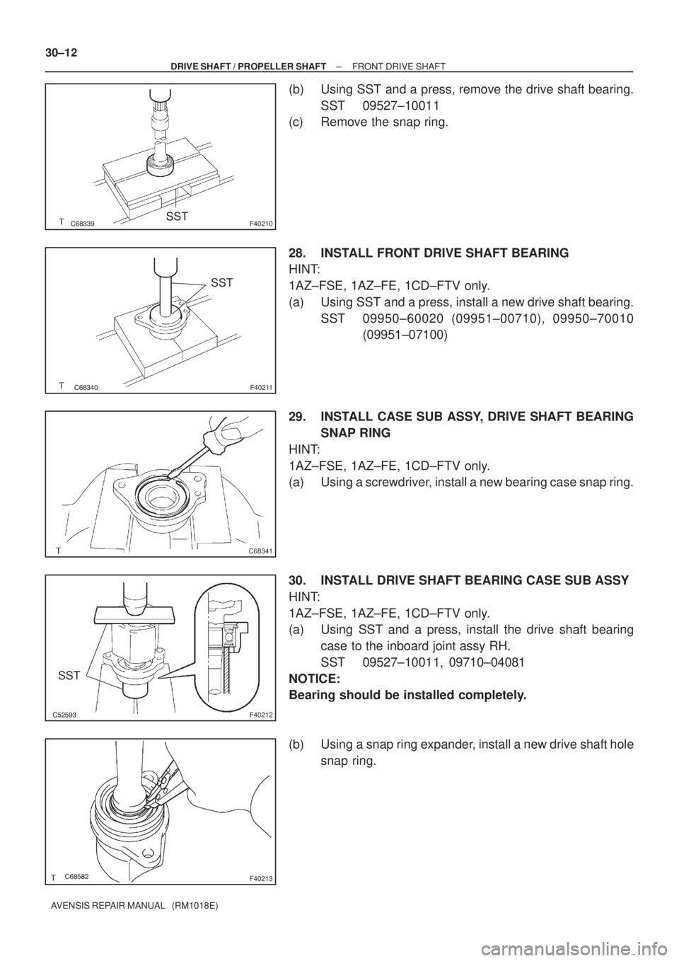
(b) Using SST and a press, remove the drive shaft bearing.
SST 09527±10011
(c) Remove the snap ring.
28. INSTALL FRONT DRIVE SHAFT BEARING
HINT:
1AZ±FSE, 1AZ±FE, 1CD±FTV only.
(a) Using SST and a press, install a new drive shaft bearing.
SST 09950±60020 (09951±00710), 09950±70010
(09951±07100)
29. INSTALL CASE SUB ASSY, DRIVE SHAFT BEARING
SNAP RING
HINT:
1AZ±FSE, 1AZ±FE, 1CD±FTV only.
(a) Using a screwdriver, install a new bearing case snap ring.
30. INSTALL DRIVE SHAFT BEARING CASE SUB ASSY
HINT:
1AZ±FSE, 1AZ±FE, 1CD±FTV only.
(a) Using SST and a press, install the drive shaft bearing
case to the inboard joint assy RH.
SST 09527±10011, 09710±04081
NOTICE:
Bearing should be installed completely.
(b) Using a snap ring expander, install a new drive shaft hole
snap ring.
Page 2544 of 5135

35. INSTALL OUTBOARD JOINT BOOT
HINT:
Before installing the")
W01994
Vinyl Tape
R10425
SSTHold
Turn
R10426
SST
30±14
± DRIVE SHAFT / PROPELLER SHAFTFRONT DRIVE SHAFT
AVENSIS REPAIR MANUAL (RM1018E)
35. INSTALL OUTBOARD JOINT BOOT
HINT:
Before installing the boots, wrap the spline of the drive shaft
with vinyl tape to prevent the boots from being damaged.
(a) Install new parts to the outboard joint shaft assy in the fol-
lowing order.
(1) Outboard joint boot LH No.2 clamp
(2) Outboard joint boot
(3) Outboard joint boot LH clamp
(b) Pack the outboard joint shaft and boot with grease in the
boot kit.
Grease capacity:
Engine typeGrease capacity g (oz.)
1AZ±FSE, 1AZ±FE, 1CD±FTV152 ± 162 g
(5.4 ± 5.7 oz.)
3ZZ±FE, 1ZZ±FE85 ± 105 g
(3.0 ± 3.7 oz.)
36. INSTALL FRONT AXLE OUTBOARD JOINT BOOT
CLAMP
(a) Hold the front drive shaft in a soft vise.
(b) Secure the 2 outboard joint boot clamps onto the boot.
(c) Place SST onto the outboard joint large boot clamp.
SST 09521±24010
(d) Tighten the SST so that the large clamp is pinched.
NOTICE:
Do not overtighten the SST.
(e) Using SST, adjust the clearance of the large clamp.
SST 09240±00020
Clearance: 0.8 mm (0.031 in.) or less
(f) Install the outboard joint boot LH clamp by the same pro-
cedures as the outboard joint boot LH No.2 clamp.
NOTICE:
When the measured value exceeds the specified value, re-
tighten the clamp.
Page 2546 of 5135

(5) Using SST, adjust the clearance of the damper
clamp.
SST 09240±00020
Cleara")
C86268
SST
C67417
Matchmarks
30±16
± DRIVE SHAFT / PROPELLER SHAFTFRONT DRIVE SHAFT
AVENSIS REPAIR MANUAL (RM1018E)
(5) Using SST, adjust the clearance of the damper
clamp.
SST 09240±00020
Clearance: 0.8 mm (0.031 in.) or less
NOTICE:
When the measured value exceeds the specified value, re-
tighten the clamp.
HINT:
�Install the damper clamp to inboard joint side.
�Except 1AZ±FSE, FE (MT)/ 1CD±FTV
�Perform the above procedure only when reassembling
the RH side
38. INSTALL FRONT DRIVE INBOARD JOINT ASSY LH
(a) Wrap the spline of the outboard joint shaft assy LH with
vinyl tape to prevent them from being damaged.
(b) Install new parts to the outboard joint shaft assy LH in the
following order.
(1) Inboard joint boot LH clamp
(2) Inboard joint boot
(3) Inboard joint boot LH No.2 clamp
(c) Place the beveled side of the tripod axial spline toward the
outboard joint.
(d) Align the matchmarks placed before removal.
(e) Using a brass bar and hammer, tap in the tripod joint assy
to the drive shaft assy LH.
NOTICE:
�Do not tap the roller.
�Be sure to install the tripod joint assy in the correct
direction.
(f) Pack the inboard joint shaft and boot with grease in the
boot kit.
Engine typeGrease capacity g (oz.)
1AZ±FSE, 1AZ±FE, 1CD±FTV170 ± 190 g
(6.0 ± 6.7 oz.)
3ZZ±FE, 1ZZ±FE125.5 ± 135.5 g
(4.4 ± 4.8 oz.)
Page 2547 of 5135

(g) Using a snap ring expander, install a new s")
G24058
������F45461
Matchmarks
C86269
SST
Hold
Turn
C86270SST
± DRIVE SHAFT / PROPELLER SHAFTFRONT DRIVE SHAFT
30±17
AVENSIS REPAIR MANUAL (RM1018E)
(g) Using a snap ring expander, install a new shaft snap ring.
(h) Aligning the matchmarks, install the inboard joint assy LH
to the outboard joint shaft assy LH.
39. INSTALL FR AXLE INBOARD JOINT BOOT
(a) Install the inboard joint boot to the inboard joint assy LH and outboard joint shaft assy LH.
40. INSTALL FRONT AXLE INBOARD JOINT BOOT
CLAMP
(a) Install the inboard joint boot clamp.
(1) Hold the drive shaft in a soft vise.
(2) Secure the 2 inboard joint boot clamps onto the
boot.
(3) Place SST onto the inboard joint large boot clamp.
SST 09521±24010
(4) Tighten the SST so that the large clamp is pinched.
NOTICE:
Do not overtighten the SST.
(5) Using SST, adjust the clearance of the large clamp.
SST 09240±00020
Clearance: 0.8 mm (0.031 in.) or less
NOTICE:
When the measured value exceeds the specified value, re-
tighten the clamp.
(b) Install the inboard joint boot LH clamp by the same proce-
dures as the inboard joint boot LH No.2 clamp.
Page 2548 of 5135

C83851
C83155
1AZ±FSE/
1AZ±FE:
F44774
1CD±FTV: 30±18
± DRIVE SHAFT / PROPELLER SHAFTFRONT DRIVE SHAFT
AVENSIS REPAIR MANUAL (RM1018E)
41. INSPECT FRONT DRIVE SHAFT
(a) C")
C91598
������F45254
(A)
C83851
C83155
1AZ±FSE/
1AZ±FE:
F44774
1CD±FTV: 30±18
± DRIVE SHAFT / PROPELLER SHAFTFRONT DRIVE SHAFT
AVENSIS REPAIR MANUAL (RM1018E)
41. INSPECT FRONT DRIVE SHAFT
(a) Check that there is no remarkable play in the radial direc-
tion of the outboard joint.
(b) Check that the inboard joint slides smoothly in the thrust
direction.
(c) Check that there is no remarkable play in the radial direc-
tion of the inboard joint.
(d) Check the boots for damage.
NOTICE:
Keep the drive shaft assy level during inspection.
HINT:
For dimension (A), refer to the following table.
Engine typeLH mm (in.)RH mm (in.)
3ZZ±FE583.8 (22.98) � 5.0 (0.20)856.3 (33.71) � 5.0 (0.20)
1ZZ±FE582.9 (22.94) � 5.0 (0.20)855.4 (33.68) � 5.0 (0.20)
1AZ±FSE, 1AZ±FE559.8 (22.03) � 5.0 (0.20)876.0 (34.49) � 5.0 (0.20)
1CD±FTV546.8 (21.53) � 5.0 (0.20)889.0 (35.00) � 5.0 (0.20)
42. INSTALL FRONT DRIVE SHAFT ASSY LH
(a) Coat the spline of the inboard joint shaft assy LH with gear
oil.
(b) Aligh the shaft splines and install the drive shaft assy LH
with a brass bar and hammer.
NOTICE:
�Set the snap ring with the opening side facing down-
wards.
�Be careful not to damage the oil seal, boot and dust
cover.
43. INSTALL FRONT DRIVE SHAFT ASSY RH
HINT:
1AZ±FSE, 1AZ±FE, 1CD±FTV only.
(a) Coat the spline of the inboard joint shaft assy RH with
gear oil.
(b) Aline the shaft splines and install the drive shaft assy RH
with the 2 bolts.
Torque: 64 N�m (650 kgf�cm, 47 ft�lbf)
NOTICE:
Do not damage the oil seal, boot and dust cover.
Page 2549 of 5135

44. INSTALL FRONT AXLE ASSY LH
(a) Install the drive shaft assy LH to the front axle ass")
C80293
F44775
C80291
± DRIVE SHAFT / PROPELLER SHAFTFRONT DRIVE SHAFT
30±19
AVENSIS REPAIR MANUAL (RM1018E)
44. INSTALL FRONT AXLE ASSY LH
(a) Install the drive shaft assy LH to the front axle assy LH.
NOTICE:
�Be careful not to damage the outboard joint boot.
�Be careful not to damage the speed sensor rotor.
45. INSTALL FRONT SUSPENSION ARM SUB±ASSY
LOWER NO.1 LH
(a) Install the lower ball joint to the front suspension arm sub±
assy lower No.1 LH with the bolt and 2 nuts.
Torque: 89 N�m (908 kgf�cm, 66 ft�lbf)
46. INSTALL TIE ROD END SUB±ASSY LH
(a) Install the tie rod end sub±assy LH to the steering knuckle with the nut.
Torque: 49 N�m (500 kgf�cm, 36 ft�lbf)
(b) Install a new cotter pin.
NOTICE:
If the holes for the cotter pin are not aligned, tighten the nut up to 60� further.
47. CONNECT SPEED SENSOR FRONT LH
(a) Install the speed sensor front LH to the steering knuckle
with the bolt.
Torque: 8.0 N�m (82 kgf�cm, 71 in.�lbf)
(b) Connect the speed sensor wire and flexible hose to the
shock absorber with the bolt.
Torque: 19 N�m (194 kgf�cm, 14 ft�lbf)
NOTICE:
�Be careful not to damage the speed sensor.
�Keep the speed sensor clean.
�Do not twist the sensor wire when installing the sen-
sor.
Page 2550 of 5135

48.INSTALL FRONT STABILIZER LINK ASSY LH
(a)Install the front stabilizer link assy LH")
F13686
HoldTurn
C68609
30±20
±
DRIVE SHAFT / PROPELLER SHAFT FRONT DRIVE SHAFT
AVENSIS REPAIR MANUAL (RM1018E)
48.INSTALL FRONT STABILIZER LINK ASSY LH
(a)Install the front stabilizer link assy LH with the nut. Torque: 74 N �m (755 kgf �cm, 55 ft �lbf)
HINT:
If the ball joint turns together with the nut, use a hexagon
wrench (6 mm) to hold the stud.
49.INSTALL FRONT AXLE HUB LH NUT
(a)Install a new axle hub LH nut. Torque: 216 N �m (2,200 kgf �cm, 159 ft �lbf)
(b)Using a chisel and hammer, stake the axle hub LH nut.
50.INSTALL ENGINE UNDER COVER LH
51.INSTALL FRONT WHEEL Torque: 103 N �m (1,050 kgf �cm, 76 ft �lbf)
52.ADD AUTOMATIC TRANSAXLE FLUID (A/T TRANSAXLE)
53.INSPECT AND ADJUST AUTOMATIC TRANSAXLE FLUID (A/T TRANSAXLE) (See page 40±2)
54. ADD MANUAL TRANSAXLE OIL (M/T TRANSAXLE)
55.INSPECT MANUAL TRANSAXLE OIL (M/T TRANSAXLE) (See page 41±2)
56.INSPECT AND ADJUST FRONT WHEEL ALIGNMENT (See page 26±6)
57. CHECK ABS SPEED SENSOR SIGNAL
(a)ABD WITH EBD SYSTEM (See page 05±699)
(b)ABD WITH EBD & BA & TRC & VSC SYSTEM ( See page 05±756)
Page 2551 of 5135
300JW±01
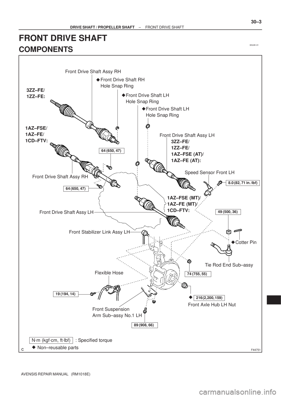
F44751
N�m (kgf�cm, ft�lbf) : Specified torque
Non±reusable parts �Front Suspension
Arm Sub±assy No.1 LH
89 (908, 66)
19 (194, 14)
74 (755, 55)
64 (650, 47)
49 (500, 36)
216 (2,200, 159)�
Front Axle Hub LH Nut Flexible Hose
Tie Rod End Sub±assy�Cotter Pin �Front Drive Shaft RH
Hole Snap Ring Front Drive Shaft Assy RH
Front Drive Shaft Assy RH 1AZ±FSE/
1AZ±FE/
1CD±FTV:
Speed Sensor Front LH
8.0 (82, 71 in.�lbf)
Front Drive Shaft Assy LH
Front Stabilizer Link Assy LH
3ZZ±FE/
1ZZ±FE:
64 (650, 47)
Front Drive Shaft Assy LH
3ZZ±FE/
1ZZ±FE/
1AZ±FSE (AT)/
1AZ±FE (AT):
1AZ±FSE (MT)/
1AZ±FE (MT)/
1CD±FTV:
�Front Drive Shaft LH
Hole Snap Ring
�Front Drive Shaft LH
Hole Snap Ring
± DRIVE SHAFT / PROPELLER SHAFTFRONT DRIVE SHAFT
30±3
AVENSIS REPAIR MANUAL (RM1018E)
FRONT DRIVE SHAFT
COMPONENTS