Page 378 of 5135
A76869
Engine Room R/B No.1
Engine Room J/B No.1
EFI
12
1 1A1
B±G
4A
4B 11
Engine
Room J/B No.4
B±G
FL MAIN
Battery
EFBR B±Y
IE3
IO1 77
(LHD)(RHD)B±Y3
E9 BATTECM
E1 7
E12
A66054
Engine Room R/B No.1
EFI Fuse
05±262
± DIAGNOSTICSSFI SYSTEM (1AZ±FE)
AVENSIS REPAIR MANUAL (RM1018E)
ECM BACK±UP POWER SOURCE CIRCUIT
CIRCUIT DESCRIPTION
While the ignition switch is OFF, the battery positive voltage is supplied to terminal BATT of the ECM for the
DTCs memory and air±fuel ratio adaptive control value memory, etc.
WIRING DIAGRAM
INSPECTION PROCEDURE
1 CHECK FUSE(EFI FUSE)
(a) Remove the EFI fuse from the engine room R/B No.1.
(b) Check for continuity in the EFI fuse.
Standard: Continuity
NG CHECK FOR SHORT IN ALL HARNESSES AND
COMPONENTS CONNECTED FUSE
OK
05C78±01
Page 386 of 5135

A73819A±A SectionAirSolid Electrolyte
(Zirconia Element)
Platinum
Electrode Heater
Exhaust Gas
Cover Element
A
A
ECM Monitored
A/F Sensor Voltage
Air±Fuel Ratio
± DIAGNOSTICSSFI SYSTEM (1AZ±FE)
05±249
AVENSIS REPAIR MANUAL (RM1018E)
DTC P2255/28 OXYGEN SENSOR REFERENCE GROUND
CIRCUIT LOW (FOR A/F SENSOR)(BANK 2
SENSOR 1)
DTC P2256/28 OXYGEN SENSOR REFERENCE GROUND
CIRCUIT HIGH (FOR A/F SENSOR)(BANK 2
SENSOR 1)
CIRCUIT DESCRIPTION
HINT:
This DTC is recorded when A/F sensor has a malfunction, although the caption is healed oxygen sensor.
The air±fuel ratio sensor are the lamination type. Compared to the conventional type, the sensor and heater
portions of the lamination type are narrower overall. Because the heat of the heater acts directly on the alumi-
na and zirconia (of the sensor portion) it accelerates the activation of the sensor.
To obtain a high purification rate of the CO, HC and NOx components of the exhaust gas, a three±way cata-
lytic converter is used. For the most efficient use of the three±way catalytic converter, the air±fuel ratio must
be precisely controlled so that it is always close to the stoichiometric air±fuel ratio.
The A/F sensor has the characteristic that it provides output voltage* being approximately proportional to
the existing air±fuel ratio. The A/F sensor output voltage* is used to provide feedback for the ECM to control
the air±fuel ratio.
By the A/F sensor output, the ECM can determine the deviation amount from the stoichiometric air±fuel ratio
and control the proper injection time immediately. If the A/F sensor is out of order, ECM is unable to perform
the accurate air±fuel ratio control.
The A/F sensor is equipped with a heater which heats the zirconia element. The heater is controlled by the
ECM. When the intake air volume is low (the temperature of the exhaust gas is low), the current flows to the
heater to heat the sensor for the accurate oxygen concentration detection.
*: The voltage value changes at the inside of the ECM only.
Page 390 of 5135

+25 %
±12.5 %
More than 3.35 V
Less than 3.0 V
Case 1
Case 2
Case 3
Case 4
Output voltage of A/F sensor
(sensor 1)
Injection volume
Output voltage
Output voltage of heated oxygen
sensor (sensor 2)Mainly suspect
trouble area
OK
+25 %
±12.5 %
More than 3.35 V
Less than 3.0V
Injection volume
Output voltage
+25 %
±12.5 %
More than 0.55 V
Less than 0.4V
Injection volume
Output voltage
A/F sensor
(A/F sensor, heater, A/F sen-
sor circuit)
+25 %
±12.5 %
More than 0.55 V
Less than 0.4V
Injection volume
Output voltage
+25 %
±12.5 %
Injection volume
Output voltage
NG
+25 %
±12.5 %
Injection volume
Output voltage
NG
+25 %
±12.5 %
Injection volume
Output voltage
NG
+25 %
±12.5 %
Injection volume
Output voltage
NGExtremely rich or lean actual
air±fuel ratio
(Injector, fuel pressure, gas
leakage in exhaust system,
etc.) OK
OK
OK
No reaction
No reaction
No reaction No reaction
�
Heated oxygen sensor
(heated oxygen sensor,
heater, heated oxygen sensor
circuit)
± DIAGNOSTICSSFI SYSTEM (1AZ±FE)
05±253
AVENSIS REPAIR MANUAL (RM1018E)
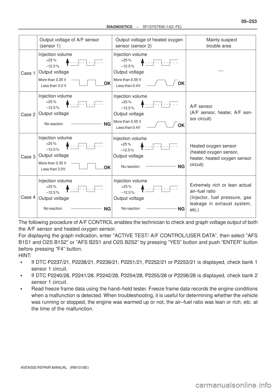
The following procedure of A/F CONTROL enables the technician to check and graph voltage output of both
the A/F sensor and heated oxygen sensor.
For displaying the graph indication, enter ºACTIVE TEST/ A/F CONTROL/USER DATAº, then select ºAFS
B1S1 and O2S B1S2º or ºAFS B2S1 and O2S B2S2º by pressing ºYESº button and push ºENTERº button
before pressing ºF4º button.
HINT:
�If DTC ��������� ��������� ����
���� ��� ����� ��� ���� �� ��� ���� is displayed, check bank 1
sensor 1 circuit.
�If DTC ��������� ��������� ��������� ��� ����� ��� ��� �� ���
��� is displayed, check bank 2
sensor 1 circuit.
�Read freeze frame data using the hand±held tester. Freeze frame data records the engine conditions
when a malfunction is detected. When troubleshooting, it is useful for determining whether the vehicle
was running or stopped, the engine was warmed up or not, the air±fuel ratio was lean or rich, etc. at
the time of the malfunction.
Page 391 of 5135
A75325
HT
AF+ +B
AF±
Bank 1, Sensor 1 A7
A/F Sensor
A79112
Bank 2, Sensor 1 A8
A/F SensorHT
AF+ +B
AF±
B16200
05±254
± DIAGNOSTICSSFI SYSTEM (1AZ±FE)
AVENSIS REPAIR MANUAL (RM1018E)
1 INSPECT AIR FUEL RATIO SENSOR(RESISTANCE OF A/F SENSOR HEATER)
(a) Disconnect the A/F sensor connector.
(b) Measure resistance between terminals HT and +B of the
A/F sensor.
Resistance: 1.8 to 3.4 � (20�C)
NG REPLACE AIR FUEL RATIO SENSOR
OK
2 INSPECT A/F RELAY
(a) Remove the A/F sensor heater relay from the engine
room R/B.
(b) Inspect the A/F senor heater relay.
Standard:
Terminal No.Specified condition
1 ± 2Continuity
No Continuity
3 ± 5Continuity
(Apply battery voltage Terminals 1 and 2)
NG REPLACE A/F RELAY
OK
Page 394 of 5135
±
DIAGNOSTICS SFI SYSTEM(1AZ±FE)
05±247
AVENSIS REPAIR MANUAL (RM1018E)
DTCP0606/89ECM/PCM PROCESSOR
CIRCUIT DESCRIPTION
DTC No.DTC Detection ConditionTrouble Area
P0606/89ECM inside error�ECM
INSPECTION PROCEDURE
HINT:
Read freeze frame data using \f���� ����\b�\f��\f�
� Freeze frame data records the engine conditions when
a malfunction is detected. When troubleshooting, it is useful for determi\
ning whether the vehicle was running
or stopped, the engine was warmed up or not, the air±fuel ratio was lea\
n or rich, etc. at the time of the mal-
function.
CHECK AND REPLACE ECM (See page 01±32)
05C75±01
Page 395 of 5135

A58697
Intake Air
Chamber
Throttle Valve
To Cylinder
ISC Valve
Valve
ECM
Signal From
Air
Cleaner
From
Terminal 2 of
EFI No.1 Fuse
(See Page 05±257)
A79101
2 +B DUTY1
GND 3
I10
ISC Valve
G±R10
E12 RSDECM
B±R 12
EA1 B±R
W±B7
E12 E1
BR
EF
±
DIAGNOSTICS SFI SYSTEM (1AZ±FE)
05±243
AVENSIS REPAIR MANUAL (RM1018E)
DTC P0511/33 IDLE AIR CONTROL CIRCUIT
CIRCUIT DESCRIPTION
The rotary solenoid type idle speed control (ISC) valve is lo-
cated under the throttle body and intake air bypassing the
throttle valve is directed to the idle speed control (ISC) valve
through the passage.
In this way the intake air volume bypassing the throttle valve is
regulated, controls the engine speed.
The ECM operates the idle speed control (ISC) valve only to
perform idle±up and provide feedback for the target idling
speed.
DTC No.DTC Detecting ConditionTrouble Area
P0511/33Idle speed continues to vary greatly from target speed
(1 trip detection logic)
�Open or short in idle speed control (ISC) valve circuit
� Idle speed control (ISC) valve is stuck or closed
� A/C switch circuit
� Air induction system
� ECM
WIRING DIAGRAM
INSPECTION PROCEDURE
HINT:
Read freeze frame data using \f�� �� ����\b� \f��\f�
� Freeze frame data records the engine conditions when
a malfunction is detected. When troubleshooting, it is useful for determi\
ning whether the vehicle was running
or stopped, the engine was warmed up or not, the air±fuel ratio was lea\
n or rich, etc. at the time of the mal-
function.
05C74±01
Page 400 of 5135
A76866
Combination MeterECM
C11 V±W
SPD
17
V±W E10
J/C
18H
J10
(LHD) J20
H
(RHD) H
J10
(LHD) J20
H
(RHD)
±
DIAGNOSTICS SFI SYSTEM(1AZ±FE)
05±241
AVENSIS REPAIR MANUAL (RM1018E)
WIRING DIAGRAM
INSPECTION PROCEDURE
HINT:
Read freeze frame data using \f���� ����\b�\f��\f�
� Freeze frame data records the engine conditions when
a malfunction is detected. When troubleshooting, it is useful for determi\
ning whether the vehicle was running
or stopped, the engine was warmed up or not, the air±fuel ratio was lea\
n or rich, etc. at the time of the mal-
function.
1CHECK OPERATION OF SPEEDOMETER
(a)Drive the vehicle and check that the operation of the speedometer in the\
combination meter is normal.
HINT:
The vehicle speed sensor is operating normally if the speedometer display i\
s normal.
NGCHECK SPEEDOMETER CIRCUIT(See page 05±1500)
OK
Page 405 of 5135

A65743
E13
ECM ConnectorIGF
A54393
Wire Harness Side
Ignition Coil and Igniter Connector
IGF I1
I2I3I4
A18294ECM Connector
E1(±)
E13E12
IGF(+)
± DIAGNOSTICSSFI SYSTEM (1AZ±FE)
05±235
AVENSIS REPAIR MANUAL (RM1018E)
INSPECTION PROCEDURE
HINT:
Read freeze frame data using the hand±held tester. Freeze frame data records the engine conditions when
a malfunction is detected. When troubleshooting, it is useful for determining whether the vehicle was running
or stopped, the engine was warmed up or not, the air±fuel ratio was lean or rich, etc. at the time of the mal-
function.
1 CHECK SPARK PLUG AND SPARK OF MISFIRING CYLINDER
NG Go to step 4
OK
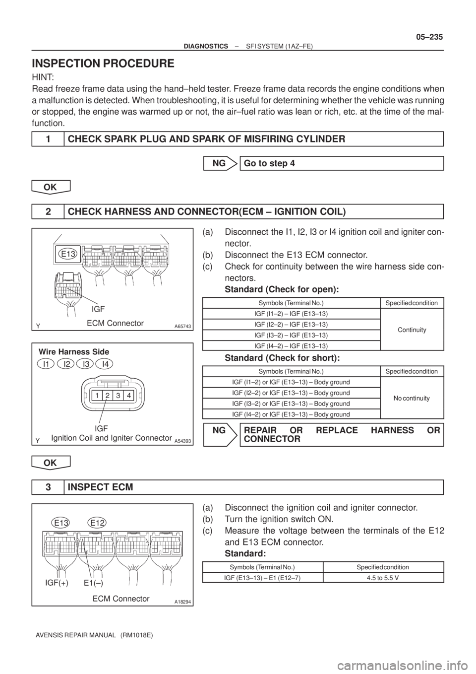
2 CHECK HARNESS AND CONNECTOR(ECM ± IGNITION COIL)
(a) Disconnect the I1, I2, I3 or I4 ignition coil and igniter con-
nector.
(b) Disconnect the E13 ECM connector.
(c) Check for continuity between the wire harness side con-
nectors.
Standard (Check for open):
Symbols (Terminal No.)Specified condition
IGF (I1±2) ± IGF (E13±13)
IGF (I2±2) ± IGF (E13±13)ContinuityIGF (I3±2) ± IGF (E13±13)Continuity
IGF (I4±2) ± IGF (E13±13)
Standard (Check for short):
Symbols (Terminal No.)Specified condition
IGF (I1±2) or IGF (E13±13) ± Body ground
IGF (I2±2) or IGF (E13±13) ± Body groundNo continuityIGF (I3±2) or IGF (E13±13) ± Body groundNo continuity
IGF (I4±2) or IGF (E13±13) ± Body ground
NG REPAIR OR REPLACE HARNESS OR
CONNECTOR
OK
3 INSPECT ECM
(a) Disconnect the ignition coil and igniter connector.
(b) Turn the ignition switch ON.
(c) Measure the voltage between the terminals of the E12
and E13 ECM connector.
Standard:
Symbols (Terminal No.)Specified condition
IGF (E13±13) ± E1 (E12±7)4.5 to 5.5 V