Page 438 of 5135

05±306
± DIAGNOSTICSSFI SYSTEM (1AZ±FSE)
AVENSIS REPAIR MANUAL (RM1018E)
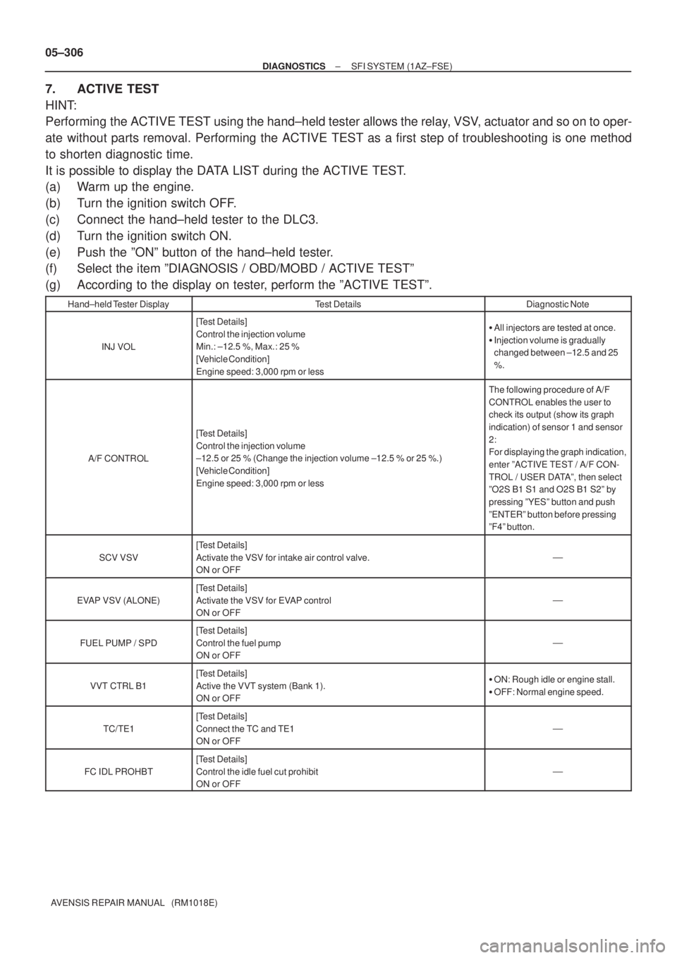
7. ACTIVE TEST
HINT:
Performing the ACTIVE TEST using the hand±held tester allows the relay, VSV, actuator and so on to oper-
ate without parts removal. Performing the ACTIVE TEST as a first step of troubleshooting is one method
to shorten diagnostic time.
It is possible to display the DATA LIST during the ACTIVE TEST.
(a) Warm up the engine.
(b) Turn the ignition switch OFF.
(c) Connect the hand±held tester to the DLC3.
(d) Turn the ignition switch ON.
(e) Push the ºONº button of the hand±held tester.
(f) Select the item ºDIAGNOSIS / OBD/MOBD / ACTIVE TESTº
(g) According to the display on tester, perform the ºACTIVE TESTº.
Hand±held Tester DisplayTest DetailsDiagnostic Note
INJ VOL
[Test Details]
Control the injection volume
Min.: ±12.5 %, Max.: 25 %
[Vehicle Condition]
Engine speed: 3,000 rpm or less�All injectors are tested at once.
�Injection volume is gradually
changed between ±12.5 and 25
%.
A/F CONTROL
[Test Details]
Control the injection volume
±12.5 or 25 % (Change the injection volume ±12.5 % or 25 %.)
[Vehicle Condition]
Engine speed: 3,000 rpm or less
The following procedure of A/F
CONTROL enables the user to
check its output (show its graph
indication) of sensor 1 and sensor
2:
For displaying the graph indication,
enter ºACTIVE TEST / A/F CON-
TROL / USER DATAº, then select
ºO2S B1 S1 and O2S B1 S2º by
pressing ºYESº button and push
ºENTERº button before pressing
ºF4º button.
SCV VSV
[Test Details]
Activate the VSV for intake air control valve.
ON or OFF
�
EVAP VSV (ALONE)
[Test Details]
Activate the VSV for EVAP control
ON or OFF
�
FUEL PUMP / SPD
[Test Details]
Control the fuel pump
ON or OFF
�
VVT CTRL B1
[Test Details]
Active the VVT system (Bank 1).
ON or OFF�ON: Rough idle or engine stall.
�OFF: Normal engine speed.
TC/TE1
[Test Details]
Connect the TC and TE1
ON or OFF
�
FC IDL PROHBT
[Test Details]
Control the idle fuel cut prohibit
ON or OFF
�
Page 440 of 5135
05±308
±
DIAGNOSTICS SFI SYSTEM(1AZ±FSE)
AVENSIS REPAIR MANUAL (RM1018E)
6CHECK IGNITION TIMING (See page 14±181)
NGPROCEED TO PAGE AND CONTINUE TO TROU- BLESHOOT
OK
PROCEED TO PROBLEM SYMPTOMS TABLE ON PAGE 05±320
7CHECK FUEL PRESSURE (See page 11±33)
NGPROCEED TO PAGE 11±33 AND CONTINUE TO TROUBLESHOOT
OK
8CHECK FOR SPARK (See page 18±12)
NGPROCEED TO PAGE 18±12 AND CONTINUE TO TROUBLESHOOT
OK
PROCEED TO PROBLEM SYMPTOMS TABLE ON PAGE 05±320
Page 445 of 5135
A76892
V3
Variable Resister
VCC 2
VA F 3
E2
1R±W
P
BR10
EA13
EA19
EA1ECM
5V
VC
VA F
E1
E2 R±W
P
BRE1318
32
E13
28
E13 05±286
± DIAGNOSTICSSFI SYSTEM (1AZ±FE)
AVENSIS REPAIR MANUAL (RM1018E)
VARIABLE RESISTOR CIRCUIT
CIRCUIT DESCRIPTION
The variable resister has been adopted to leaded±type vehicle only.
This resistor is used change the air±fuel ratio of the air±fuel mixture.
The idle mixture is adjusted using this resistor.
Turning the idle mixture adjusting screw clockwise moves the contacts inside the resistor, raising the terminal
VAF voltage. Conversely, turning the screw counterclockwise lowers the terminal VAF voltage.
When the terminal VAF voltage rises, the ECM increases the injection volume slightly, marking the air±fuel
mixture a little richer.
WIRING DIAGRAM
INSPECTION PROCEDURE
NOTICE:
Always use a CO meter when adjusting the idle mixture. If a CO meter is not available, DO NOT AT-
TEMPT TO ADJUST IDLE MIXTURE.
05C7E±01
Page 453 of 5135
A76870
ECM
STA
E129
B±Y
IJW±BJ12
B B J13
J/C W±B 1 5
32 1AM2 2
B±G
B±R1
S51S4
Starter
Battery7
IK1
FL MAIN 4B 4A
Engine Room
J/B No. 4
BB 55
55 1
11A
B±GB±R
IE41
(LHD)IP11
(RHD)B±R
Engine
Room
R/B No. 1
Engine
Room
J/B No.1
Driver
Side R/BST
Relay
2DJ
9DA Driver
Side J/B B±R
B±RI13
Ignition Switch
45B±Y
B±Y
6
2ST 1
6 Fuse
Block
B±WB±YB±Y B±Y
J12 A C J13
A
J12 1
1
(M/T)
B±W
(A/T)
N1
Neutral Start SW96B±Y
(A/T) 05±278
± DIAGNOSTICSSFI SYSTEM (1AZ±FE)
AVENSIS REPAIR MANUAL (RM1018E)
STARTER SIGNAL CIRCUIT
CIRCUIT DESCRIPTION
When the engine is cranked, the intake air flow becomes slow, so fuel vaporization is poor. A rich mixture
is therefore necessary in order to achieve good startability. While the engine is being cranked, the battery
voltage is applied to terminal STA of the ECM. The starter signal is mainly used to increase the fuel injection
volume for the starting injection control and after±start injection control.
WIRING DIAGRAM
05C7B±01
Page 457 of 5135
A78423
20V
/Division Injector Signal Waveform
20V
/Division
GND
100 msec./Division (Idling)(Magnification)
GND
1 msec./Division (Idling)
Injection duration
05±272
± DIAGNOSTICSSFI SYSTEM (1AZ±FE)
AVENSIS REPAIR MANUAL (RM1018E)
FUEL INJECTOR CIRCUIT
CIRCUIT DESCRIPTION
The fuel injectors are located on the intake manifold.
They inject fuel into the cylinders based on the signals from the ECM.
Reference: Inspection using oscilloscope
With the engine idling, check the waveform between terminals #1 to #4 and E01 of the ECM connectors.
HINT:
The correct waveform is as shown in the diagram below.
05C7A±01
Page 459 of 5135

A18294
#4#3#2#1E01
ECM Connector
E13
B16200
A79096
Driver Side J/BIGN Fuse
05±274
±
DIAGNOSTICS SFI SYSTEM(1AZ±FE)
AVENSIS REPAIR MANUAL (RM1018E)
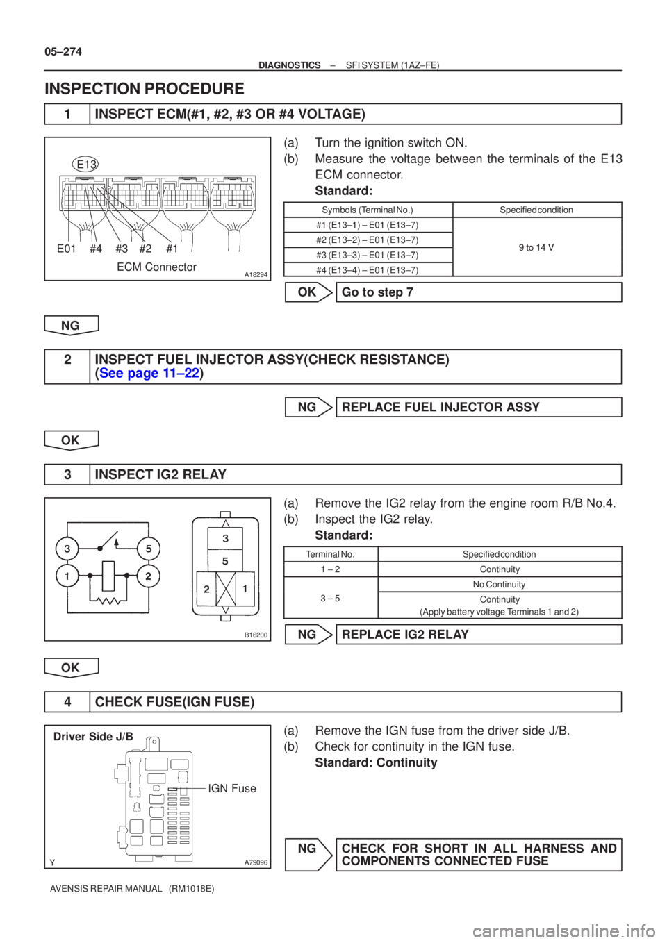
INSPECTION PROCEDURE
1INSPECT ECM(#1, #2, #3 OR #4 VOLTAGE)
(a)Turn the ignition switch ON.
(b)Measure the voltage between the terminals of the E13 ECM connector.
Standard:
Symbols (Terminal No.)Specified condition
#1 (E13±1) ± E01 (E13±7)
#2 (E13±2) ± E01 (E13±7)9to14V#3 (E13±3) ± E01 (E13±7)9 to 14 V
#4 (E13±4) ± E01 (E13±7)
OKGo to step 7
NG
2INSPECT FUEL INJECTOR ASSY(CHECK RESISTANCE) (See page 11±22)
NG REPLACE FUEL INJECTOR ASSY
OK
3 INSPECT IG2 RELAY
(a) Remove the IG2 relay from the engine room R/B No.4.
(b) Inspect the IG2 relay. Standard:
Terminal No.Specified condition
1 ± 2Continuity
No Continuity
3 ± 5Continuity
(Apply battery voltage Terminals 1 and 2)
NG REPLACE IG2 RELAY
OK
4 CHECK FUSE(IGN FUSE)
(a) Remove the IGN fuse from the driver side J/B.
(b) Check for continuity in the IGN fuse. Standard: Continuity
NG CHECK FOR SHORT IN ALL HARNESS AND COMPONENTS CONNECTED FUSE
Page 462 of 5135
A65743
E13
ECM ConnectorE02E01
±
DIAGNOSTICS SFI SYSTEM(1AZ±FE)
05±277
AVENSIS REPAIR MANUAL (RM1018E)
7INSPECT ECM
(a)Disconnect the ECM E13 connector.
(b)Check for continuity between the ECM connector and
body ground.
Standard (Check for open):
Symbols (Terminal No.)Specified condition
E01 (E13±7) ± Body groundContinuityE02 (E13±6) ± Body groundContinuity
NGREPAIR OR REPLACE HARNESS OR CONNECTOR
OK
8INSPECT FUEL INJECTOR ASSY(CHECK INJECTOR VOLUME) (See page 11±22)
NGREPLACE FUEL INJECTOR ASSY
OK
PROCEED TO NEXT CIRCUIT INSPECTION SHOWN ON PROBLEM SYMPTOMS TABLE
(See page 05±168)
Page 463 of 5135
05±362
±
DIAGNOSTICS SFI SYSTEM(1AZ±FSE)
AVENSIS REPAIR MANUAL (RM1018E)
DTCP0121THROTTLE/PEDAL POSITION SENSOR/SWITCH ºAº CIRCUIT
RANGE/PERFORMANCE PROBLEM
HINT:
This is the procedure of the ºthrottle position sensorº.
CIRCUIT DESCRIPTION
Refer to DTC P0120 on page 05±356.
DTC No.DTC Detection ConditionTrouble Area
P0121Condition (a) continues for 2.0 seconds:
(a) Difference between VTA1 and VTA2 is out of thresholdThrottle position sensor (built in throttle body)
INSPECTION PROCEDURE
HINT:
Read freeze frame data using the hand±held tester. Freeze frame data records the engine conditions when
a malfunction is detected. When troubleshooting, it is useful for determi\
ning whether the vehicle was running
or stopped, the engine was warmed up or not, the air±fuel ratio was lea\
n or rich, etc. at the time of the mal-
function.
REPLACE THROTTLE BODY ASSY
05CK8±01