Page 1214 of 5135
I36144
IG
GND
A16A15
± DIAGNOSTICSAIR CONDITIONING SYSTEM
05±1145
AVENSIS REPAIR MANUAL (RM1018E)
INSPECTION PROCEDURE
1 CHECK FUSE(HTR FUSE)
(a) Remove the HTR fuse from the driver side J/B.
(b) Check for the continuity of HTR fuse.
NG REPLACE FUSE
OK
2 CHECK HARNESS AND CONNECTOR(A/C AMPLIFIER ± BATTERY)
(a) Remove the A/C amplifier with connectors being con-
nected.
(b) Turn the ignition switch to ON.
(c) Measure the voltage between terminal IG and GND of the
A/C amplifier.
Standard: 10 to 14 V
NG REPAIR OR REPLACE HARNESS OR
CONNECTOR
OK
PROCEED TO NEXT CIRCUIT INSPECTION SHOWN ON PROBLEM SYMPTOMS TABLE
Page 1215 of 5135
I35395
Fuse Block Center J/BA/C Control Assembly
ECU±B2
66
12CC CF 10 7
W±R W±R
A1624
+B
B±W
IE4 IP145
(*3) (*4)B±W Engine Room R/B No.1 & Engine Room J/B No.1B±G (*1)
B (*2) DCC
11A
1 21
Engine Room R/B No.3
Engine Room J/B No.4
Center J/B B (*2)
B±G (*1)B (*2)
B±G (*1) 33
4A 4B
CG CA W±B (*3) W±B (*3)11
63
A1613
GND
FL MAIN
Battery
IP IKAAA W±B (*4) W±B (*4)J17
J/C
*1: Gasoline
*2: 1CD±FTV*3: LHD
*4: RHDJ15
J/C 05±1142
± DIAGNOSTICSAIR CONDITIONING SYSTEM
AVENSIS REPAIR MANUAL (RM1018E)
BACK±UP POWER SOURCE CIRCUIT
CIRCUIT DESCRIPTION
This is the back±up power source for the A/C amplifier. Power is supplied even when the ignition switch is
off and is used for diagnostic trouble code memory etc.
WIRING DIAGRAM
050TW±10
Page 1216 of 5135
I36144
+BGND
A16A15
± DIAGNOSTICSAIR CONDITIONING SYSTEM
05±1143
AVENSIS REPAIR MANUAL (RM1018E)
INSPECTION PROCEDURE
1 CHECK FUSE(ECU±B2, DCC FUSE)
(a) Remove the ECU±B2 fuse and DCC fuse from the fuse block and engine room J/B.
(b) Check for the continuity of ECU±B2 fuse and DCC fuse.
NG REPLACE FUSE
OK
2 CHECK HARNESS AND CONNECTOR(A/C AMPLIFIER ± BATTERY)
(a) Remove the A/C amplifier with being connected.
(b) Measure the voltage between terminal +B and GND of
A/C amplifier.
Standard: 10 to 14 V
NG REPAIR OR REPLACE HARNESS OR
CONNECTOR
OK
PROCEED TO NEXT CIRCUIT INSPECTION SHOWN ON PROBLEM SYMPTOMS TABLE
Page 1695 of 5135

B68152
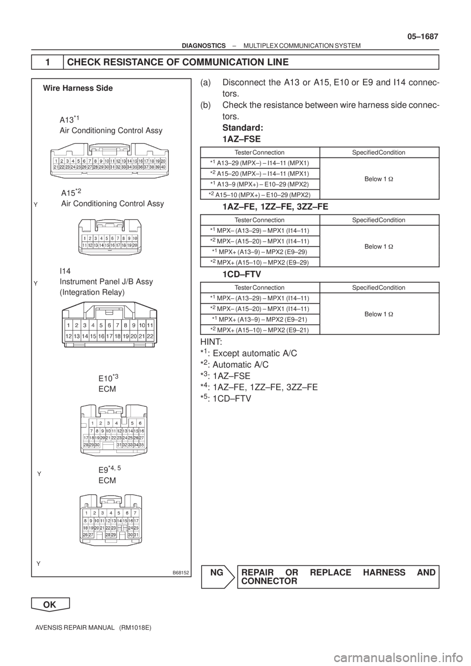
Wire Harness Side
A13
*1
Air Conditioning Control Assy
A15
*2
Air Conditioning Control Assy
I14
Instrument Panel J/B Assy
(Integration Relay)
E10
*3
ECM
E9
*4,
5
ECM
± DIAGNOSTICSMULTIPLEX COMMUNICATION SYSTEM
05±1687
AVENSIS REPAIR MANUAL (RM1018E)
1 CHECK RESISTANCE OF COMMUNICATION LINE
(a) Disconnect the A13 or A15, E10 or E9 and I14 connec-
tors.
(b) Check the resistance between wire harness side connec-
tors.
Standard:
1AZ±FSE
Tester ConnectionSpecified Condition
*1
A13±29 (MPX±) ± I14±11 (MPX1)
*2
A15±20 (MPX±) ± I14±11 (MPX1)Below 1�*1
A13±9 (MPX+) ± E10±29 (MPX2)Below 1 �
*2
A15±10 (MPX+) ± E10±29 (MPX2)
1AZ±FE, 1ZZ±FE, 3ZZ±FE
Tester ConnectionSpecified Condition
*1
MPX± (A13±29) ± MPX1 (I14±11)
*2
MPX± (A15±20) ± MPX1 (I14±11)Below 1�*1
MPX+ (A13±9) ± MPX2 (E9±29)Below 1 �
*2
MPX+ (A15±10) ± MPX2 (E9±29)
1CD±FTV
Tester ConnectionSpecified Condition
*1
MPX± (A13±29) ± MPX1 (I14±11)
*2
MPX± (A15±20) ± MPX1 (I14±11)Below 1�*1
MPX+ (A13±9) ± MPX2 (E9±21)Below 1 �
*2
MPX+ (A15±10) ± MPX2 (E9±21)
HINT:
*
1: Except automatic A/C
*
2: Automatic A/C
*
3: 1AZ±FSE
*
4: 1AZ±FE, 1ZZ±FE, 3ZZ±FE
*
5: 1CD±FTV
NG REPAIR OR REPLACE HARNESS AND
CONNECTOR
OK
Page 1696 of 5135

B68404
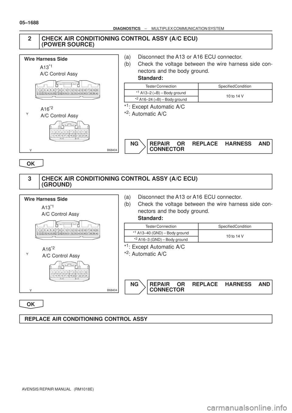
Wire Harness Side
A16
*2
A/C Control Assy A13
*1
A/C Control Assy
B68404
Wire Harness Side
A16
*2
A/C Control Assy A13
*1
A/C Control Assy
05±1688
± DIAGNOSTICSMULTIPLEX COMMUNICATION SYSTEM
AVENSIS REPAIR MANUAL (RM1018E)
2 CHECK AIR CONDITIONING CONTROL ASSY (A/C ECU)
(POWER SOURCE)
(a) Disconnect the A13 or A16 ECU connector.
(b) Check the voltage between the wire harness side con-
nectors and the body ground.
Standard:
Tester ConnectionSpecified Condition
*1
A13±2 (+B) ± Body ground10 to 14 V*2
A16±24 (+B) ± Body ground10 to 14 V
*1: Except Automatic A/C
*
2: Automatic A/C
NG REPAIR OR REPLACE HARNESS AND
CONNECTOR
OK
3 CHECK AIR CONDITIONING CONTROL ASSY (A/C ECU)
(GROUND)
(a) Disconnect the A13 or A16 ECU connector.
(b) Check the voltage between the wire harness side con-
nectors and the body ground.
Standard:
Tester ConnectionSpecified Condition
*1
A13±40 (GND) ± Body ground10 to 14 V*2
A16±3 (GND) ± Body ground10 to 14 V
*1: Except Automatic A/C
*
2: Automatic A/C
NG REPAIR OR REPLACE HARNESS AND
CONNECTOR
OK
REPLACE AIR CONDITIONING CONTROL ASSY
Page 1709 of 5135
B67972
Theft Warning ECU Assy Combination Meter Assy
(Combination Meter ECU) A/C Control Assy
(A/C ECU)Instrument Panel J/B Assy
(Integration Relay)
ECM
± DIAGNOSTICSMULTIPLEX COMMUNICATION SYSTEM
05±1677
AVENSIS REPAIR MANUAL (RM1018E)
6 CHECK DTC (A/C ECU)
(a) Check whether the output of the DTC stops when the A/C ECU connector is disconnected.
HINT:
When the output of the DTC stops, the A/C ECU is malfunctioning.
YES REPLACE AIR CONDITIONING CONTROL ASSY
(A/C ECU)
NO
Page 1710 of 5135
B67973
Theft Warning ECU Assy Combination Meter Assy
(Combination Meter ECU) Air Conditioning Control Assy
(A/C ECU)Instrument Panel J/B Assy
(Integration Relay)
ECM
E9*3 or E10*4A13*1 or A15*2
05±1678
± DIAGNOSTICSMULTIPLEX COMMUNICATION SYSTEM
AVENSIS REPAIR MANUAL (RM1018E)
7 CHECK WIRE HARNESS (A/C ECU ± ECM)
(a) Check whether the output of the DTC stops when the A13*1 or A15*2 connector of the A/C ECU and
the E10*
3 or E9*4 connector of the ECM are disconnected.
HINT:
When the output of the DTC stops, the wire harness between the
A13*1 or A15*2 connector of the A/C ECU
and the E10*
3 or E9*4 connector of the ECM is malfunctioning.
*
1: Except Automatic A/C
*
2: Automatic A/C
*
3: 1AZ±FSE
*
4: Except 1AZ±FSE
YES REPAIR OR REPLACE HARNESS AND
CONNECTOR
NO
Page 1987 of 5135

TA C
A52006
A01037
14±2
± ENGINE MECHANICALENGINE (1ZZ±FE/3ZZ±FE)
AVENSIS REPAIR MANUAL (RM1018E)
(5) Inspect ignition timing at idle.
Ignition timing: 8 to 12�BTDC
NOTICE:
When checking the ignition timing, shift the transmission
to the neutral position.
HINT:
Run the engine at 1,000 to 1,300 rpm for 5 seconds, check that
the engine rpm returns to the idle speed.
(6) Disconnect the terminal 13 (TC) and 4 (CG) of the
DLC3.
(7) Inspect ignition timing at idle.
Ignition timing:
10 to 18 �BTDC (1ZZ±FE)
3.5 to 11.5 �BTDC (3ZZ±FE)
(8) Confirm that ignition timing to go advanced angle
side when the engine rpm is increased.
(9) Remove the timing light.
(10) Install the cylinder head cover with the 2 nuts and
2 clips.
Torque: 7.0 N�m (71 kgf�cm, 62 in.�lbf)
8. INSPECT ENGINE IDLE SPEED
(a) Warm up engine.
(b) When using hand±held tester:
(1) Connect the hand±held tester to the DLC3.
HINT:
Please refer to the hand±held tester operator's manual if you
need help to select DATA LIST.
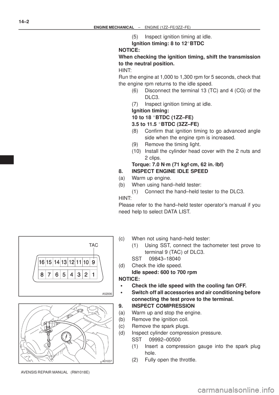
(c) When not using hand±held tester:
(1) Using SST, connect the tachometer test prove to
terminal 9 (TAC) of DLC3.
SST 09843±18040
(d) Check the idle speed.
Idle speed: 600 to 700 rpm
NOTICE:
�Check the idle speed with the cooling fan OFF.
�Switch off all accessories and air conditioning before
connecting the test prove to the terminal.
9. INSPECT COMPRESSION
(a) Warm up and stop the engine.
(b) Remove the ignition coil.
(c) Remove the spark plugs.
(d) Inspect cylinder compression pressure.
SST 09992±00500
(1) Insert a compression gauge into the spark plug
hole.
(2) Fully open the throttle.