Page 1206 of 5135
I35381
R±W
R±WR±W HF
J26 J27
IK2 IK2A15 SOL+ RR J/CC3
Compressor
Assembly
38A/C Control Assembly
(*2)
(*2)
R±W
(*1)21
Center J/B
R±W
(*1)1
CB9
CJ
Driver Side J/B
6
DCFrom
HTR
Fuse
*1: LHD
*2: RHD 2
± DIAGNOSTICSAIR CONDITIONING SYSTEM
05±1151
AVENSIS REPAIR MANUAL (RM1018E)
AIR CONDITIONER MAGNETIC VALVE CIRCUIT
CIRCUIT DESCRIPTION
The air conditioner magnetic valve is controlled by A/C amplifier.
WIRING DIAGRAM
05C7P±01
Page 1207 of 5135
I36135
05±1152
±
DIAGNOSTICS AIR CONDITIONING SYSTEM
AVENSIS REPAIR MANUAL (RM1018E)
INSPECTION PROCEDURE
1PERFORM ACTUATOR CHECK
(a)Set the actuator check mode (See page 05±1091).
(b)Press the DEF switch and change to the step operation.
(c)Check the air flow level by hand.
Display CodeBlower level
0ON
1ON
2OFF
3OFF
4OFF
5OFF
6OFF
7OFF
8OFF
9OFF
OKPROCEED TO NEXT CIRCUIT INSPECTION SHOWN ON PROBLEM SYMPTOMS TABLE
NG
2INSPECT AIR CONDITIONER MAGNETIC VALVE
(a)Measure the resistance between terminals 1 and 2. Standard: 10 to 11 � at 25 �C (77 �F)
If the resistance is not as specified, replace the compressor
assy.
NGREPLACE W/PULLEY COMPRESSOR ASSY
OK
3CHECK HARNESS AND CONNECTOR(A/C AMPLIFIER ± BATTERY)
(a)Check for an open or short circuit in harness and connector between terminal \
SOL+ of A/C amplifier and battery + terminal (See page 01±32).
NG REPAIR OR REPLACE HARNESS ORCONNECTOR
OK
REPLACE AIR CONDITIONING AMPLIFIER
Page 1208 of 5135
I36148
Duty Ratio =A + BA
x 100 (%)
ON 0 VOFF 5 VA
1 cycle Blower Level (Reference)
Si duty (%)
B HI
M8
M7
M6
M5
M4
M3
M2
M1
LO
26.3
30.937.8
44.751.6
58.465.3
74.583.7 100.0
I36133
B5
Blower Motor
Controller
A/C Control Assembly
SI
+B
VM
GND2
3
4
1LB
M
2
1 L±BL±BR
Driver Side J/B
DF2From
HTR
RELAY
L±B
J15
J/C A
IK5
A16 BLW L±B
2
IJ2
1
IJ2
4
IJ2 B±WB
W±B 3
IJ2
B4
Blower Motor
W±B 05±1148
± DIAGNOSTICSAIR CONDITIONING SYSTEM
AVENSIS REPAIR MANUAL (RM1018E)
BLOWER MOTOR CIRCUIT
CIRCUIT DESCRIPTION
The blower motor is operated by signals from the A/C amplifier. Blower motor speed signals are transmitted
by changes in the Duty Ratio.
Duty Ratio
The duty ratio is the ratio of the period of continuity in one cycle. For example, if A is the period of continuity
in one cycle, and then B is the period of non±continuity.
WIRING DIAGRAM
05C7O±01
Page 1209 of 5135
I30151
2
1
LHD
RHD
±
DIAGNOSTICS AIR CONDITIONING SYSTEM
05±1149
AVENSIS REPAIR MANUAL (RM1018E)
INSPECTION PROCEDURE
1PERFORM ACTUATOR CHECK
(a)Set to actuator check mode (See page 05±1091).
(b)Press the DEF switch and change to step operation.
(c)Check the air flow level by hand.
Display CodeBlower level
00
11
216
316
416
516
616
716
816
931
OKPROCEED TO NEXT CIRCUIT INSPECTION
SHOWN ON PROBLEM SYMPTOMS TABLE
NG
2INSPECT BLOWER W/FAN MOTOR SUB±ASSY
(a)Connect the positive (+) lead from the battery to terminal 1 and negative (±) to terminal 2.
Standard: Blower motor operates smoothly.
If operation is not as specified, replace the blower motor.
NGREPLACE BLOWER W/FAN MOTOR SUB±ASSY
OK
3CHECK HARNESS AND CONNECTOR(BLOWER W/FAN MOTOR SUB±ASSY ± BLOWER MOTOR CONTROL)
(a)Check for an open or short circuit in harness and connector between blow\
er w/fan motor sub±assy
and blower motor control (See page 01±32).
NG REPAIR OR REPLACE HARNESS ORCONNECTOR
OK
Page 1210 of 5135

4CHECK HARNESS AND CONNECTO")
������I37588
B5
GND
1234
I36144
BLW
A16A15
I31456
GND
2V/
Division
500 �s sec. / Division
05±1150
±
DIAGNOSTICS AIR CONDITIONING SYSTEM
AVENSIS REPAIR MANUAL (RM1018E)
4CHECK HARNESS AND CONNECTOR(BLOWER MOTOR CONTROL ± BODY GROUND)
(a)Check for an open circuit in harness and connector be-
tween terminal GND of blower motor control and body
ground (See page 01±32).
NGREPAIR OR REPLACE HARNESS OR CONNECTOR
OK
5INSPECT AIR CONDITIONING AMPLIFIER(BLW)
(a)Remove the A/C amplifier with connectors being con- nected.
(b)Turn the ignition switch ON.
(c)Blower switch is ON.
(d)Measure the waveform between terminal BLW of A/C am- plifier and body ground.
OK: Pulse generation
HINT:
�The correct waveform is as shown.
�Waveform varies with blower level.
NGREPLACE AIR CONDITIONING AMPLIFIER
OK
6CHECK HARNESS OR CONNECTOR(A/C AMPLIFIER ± BLOWER MOTOR CONTROL)
(a)Check for an open or short circuit in harness and connector between A/C amplifier and\
blower motor
control (See page 01±32).
NG REPAIR OR REPLACE HARNESS ORCONNECTOR
OK
REPLACE BLOWER MOTOR CONTROL
Page 1211 of 5135
I35394
Driver Side J/B
L2
DP
1
DN
5
DH B±G (*1)
B±L (*2)
G±Y9
DA
1
DH4
DF2
DF34
DA HTR HTR Relay
12
53
4L±B
To
Blower Motor GR±R
W±BA1617 A/C Control Assembly
HR
W±B
AM153
12IG1 Relay
I13
Ignition SW
G±R G±Y
AM1 IG1 1 3
G±Y
B±L (*2)1
ED1W (*2)Engine Room R/B No.3
3
3140A
ALT
1 23B (*2)
B±G (*1)W (*2) Engine Room R/B
No.1 & Engine Room J/B No.1
L
11B1 HTR
1 2
Engine Room R/B No.4
1
4C
4D1120A ALT (*3)
100A ALT (*4)
4B1
B±G (*1)
B (*2)
W±B
W±B FL MAIN
BatteryIJ
*1: Gasoline
*2: 1CD±FTV*3: 1AZ±FSE, 1AZ±FE
*4: 1ZZ±FE, 3ZZ±FE 05±1146
± DIAGNOSTICSAIR CONDITIONING SYSTEM
AVENSIS REPAIR MANUAL (RM1018E)
HEATER RELAY CIRCUIT
CIRCUIT DESCRIPTION
The heater relay is switched on by signals from the A/C amplifier. It supplies power to the blower motor.
WIRING DIAGRAM
050U2±12
Page 1212 of 5135

INSPECTION PROCEDURE
1 CHECK FUSE(HTR FUSE)
(a) Remove the HTR fuse from the driver side J/B an")
E32993
I36144
HR
A16A15
± DIAGNOSTICSAIR CONDITIONING SYSTEM
05±1147
AVENSIS REPAIR MANUAL (RM1018E)
INSPECTION PROCEDURE
1 CHECK FUSE(HTR FUSE)
(a) Remove the HTR fuse from the driver side J/B and engine room J/B.
(b) Check for the continuity of HTR fuse.
NG REPLACE FUSE
OK
2 INSPECT HEATER RELAY
(a) Check for the continuity between each pair of terminals of
cooler relay assy, as shown in the chart.
Standard:
Terminal No.Specified condition
No continuity
3 ± 5Less than 1 �
(When battery voltage applied to terminals 1 and 2)
Less than 1 �
3 ± 4No continuity
(When battery voltage applied to terminals 1 and 2)
1 ± 2Approx. 1.3 k�
NG REPLACE HEATER RELAY
OK
3 CHECK HARNESS AND CONNECTOR(A/C AMPLIFIER ± BATTERY)
(a) Remove the A/C amplifier with connectors being con-
nected.
(b) Measure the voltage between terminal HR of A/C amplifi-
er and body ground when ignition switch is ON and OFF.
Standard:
Ignition switch positionBlower switch positionVoltage (V)
OFFOFF0
ONONBelow 1.0
ONOFF10 to 14
NG REPAIR OR REPLACE HARNESS OR
CONNECTOR
OK
PROCEED TO NEXT CIRCUIT INSPECTION SHOWN ON PROBLEM SYMPTOMS TABLE
Page 1213 of 5135
������
I36744
Driver Side J/BA/C Control Assembly
1
DN6
DC AM1
HTR1
DH
5
DH9
DAW±BR±W
(*3)R±W
(*4)J26 J26R±W
(*4) HHJ/C
1
CB2
CER±W
(*3)A1612
IG
I13 Ignition SW
G±Y G±R
IG1 AM1 13Center J/B
6
CA3
CGW±B
(*3)A1613
GND Center J/B
B±G
(*1)53
12
1
4D
1 2 120A ALT (*5)
1
4B
3
1 2 140A ALT
3 B±L
(*2)ED11
W
(*2)
B
(*2)
B±G
(*1)
FL MAIN
Battery
IJ IP IK *1: Gasoline
*2: 1CD±FTV
*3: LHD
*4: RHD
*5: 1AZ±FSE, 1AZ±FE
*6: 1ZZ±FE, 3ZZ±FEW±B
(*4)
A
J15
J/C W±B
(*3) IG1 Relay
Engine Room R/B No.4
Engine Room R/B No.3100A ALT (*6)
W±B
(*4)J17
J/C
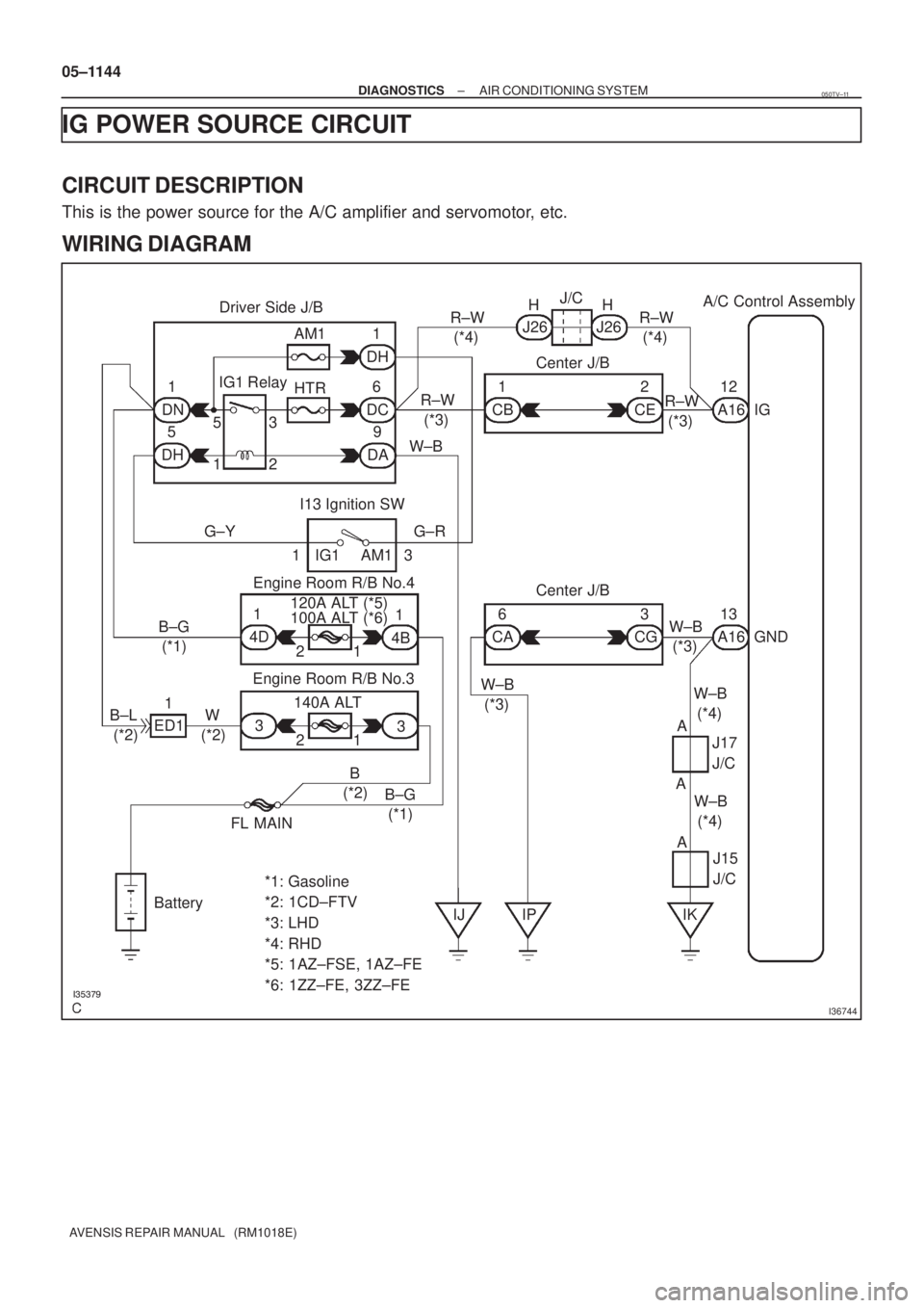
AA 05±1144
± DIAGNOSTICSAIR CONDITIONING SYSTEM
AVENSIS REPAIR MANUAL (RM1018E)
IG POWER SOURCE CIRCUIT
CIRCUIT DESCRIPTION
This is the power source for the A/C amplifier and servomotor, etc.
WIRING DIAGRAM
050TV±11

(*2)
R±W
(*1)21
Center J/B
R±W
(*1)1
CB9
CJ
Driver Side J/B
6
DCFrom
HTR
Fuse
*1: LHD
*2:")

INSPECTION PROCEDURE
1PERFORM ACTUATOR CHECK
(a)Set the actuator check mode (See page 05±1091).
(b)Press the D")

ON 0 VOFF 5 VA
1 cycle Blower Level (Reference)
Si duty (%)
B HI
M8
M7
M6
M5
M4
M3
M2
M1
LO
26.3
30.937.8
44.751.6
58.465.3
74.583.7 100.0
I36133
B5
Blower Motor
C")

INSPECTION PROCEDURE
1PERFORM ACTUATOR CHECK
(a)Set to actuator check mode (See page 05±1091).
(b)")

B±L (*2)
G±Y9
DA
1
DH4
DF2
DF34
DA HTR HTR Relay
12
53
4L±B
To
Blower Motor GR±R
W±BA1617 A/C Control Assembly
HR
W±B
AM153
12IG1 Relay
I13
Ign")