Page 4628 of 5135

SST
A09620
A85427
TDC Mark
Dot Mark90_
A09624
A09625
14−154
− ENGINE MECHANICALCAMSHAFT (1CD−FTV)(From September, 2003)
AVENSIS Supplement (RM1045E)
45. INSTALL CAMSHAFT OIL SEAL
(a) Using SST and a hammer, tap in a new oil seal until its sur-
face is flush with the camshaft oil seal retainer edge.
SST 09223−46011
(b) Apply multipurpose grease to a new oil seal lip.
NOTICE:
Keep the lip free of foreign object.
46. SET NO. 1 CYLINDER TO TDC/COMPRESSION
(a) Using the crankshaft pulley bolt, turn the crankshaft to set
the dot mark of the crankshaft timing gear at the position
of 90_BTDC.
NOTICE:
If the timing belt is disengaged, the crankshaft timing gear
placed at wrong angle can cause contact of the piston head
with the valve head.
47. INSTALL CAMSHAFT
NOTICE:
Since the thrust clearance of the camshaft is small, the
camshaft must be kept level while being installed. If the
camshaft is not kept level, the cylinder head or camshaft
may be damaged. To avoid this, the following procedures
should be carried out.
(a) Place the camshaft carrier on the cylinder head.
(b) Install the camshaft.
(c) Apply engine oil to the cam and gear of the camshaft, and
the journal of the camshaft carrier.
(d) Place the intake camshaft on the camshaft carrier so that
the No. 3 and No. 4 of the cylinder cam lobes face down-
ward as shown in the illustration.
Page 4629 of 5135

A09626
Alignment Mark
A09601
Seal Packing
A09627
A09650
12
3
5
49
6
8
7
13
10
11
15
14 12
−
ENGINE MECHANICAL CAMSHAFT (1CD−FTV)(From September, 2003)
14 −155
AVENSIS Supplement (RM1045E)
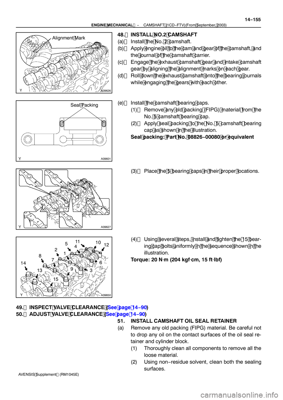
48. INSTALL NO.2 CAMSHAFT
(a) Install the No. 2 camshaft.
(b) Apply engine oil to the cam and gear of the camshaft, and
the journal of the camshaft carrier.
(c) Engage the exhaust camshaft gear and intake camshaft gear by aligning the alignment marks on each gear.
(d) Roll down the exhaust camshaft onto the bearing journals while engaging the gears with each other.
(e) Install the camshaft bearing caps. (1) Remove any old packing (FIPG) material from the No. 5 camshaft bearing cap.
(2) Apply seal packing to the No. 5 camshaft bearing cap as shown in the illustration.
Seal packing: Part No. 08826 −00080 or equivalent
(3) Place the 5 bearing caps in their proper locations.
(4) Using several steps, install and tighten the 15 bear- ing cap bolts uniformly in the sequence shown in the
illustration.
Torque: 20 N �m (204 kgf �cm, 15 ft �lbf)
49. INSPECT VALVE CLEARANCE (See page 14 −90)
50. ADJUST VALVE CLEARANCE (See page 14 −90)
51. INSTALL CAMSHAFT OIL SEAL RETAINER
(a) Remove any old packing (FIPG) material. Be careful not to drop any oil on the contact surfaces of the oil seal re-
tainer and cylinder block.
(1) Thoroughly clean all components to remove all the loose material.
(2) Using non −residue solvent, clean both the sealing
surfaces.
Page 4630 of 5135

A85428
Seal Width
2to4mm
(0.08 to 0.16 in.)Seal Packing
A62592
SST
A85760
90_
14
−156
−
ENGINE MECHANICAL CAMSHAFT (1CD−FTV)(From September, 2003)
AVENSIS Supplement (RM1045E)
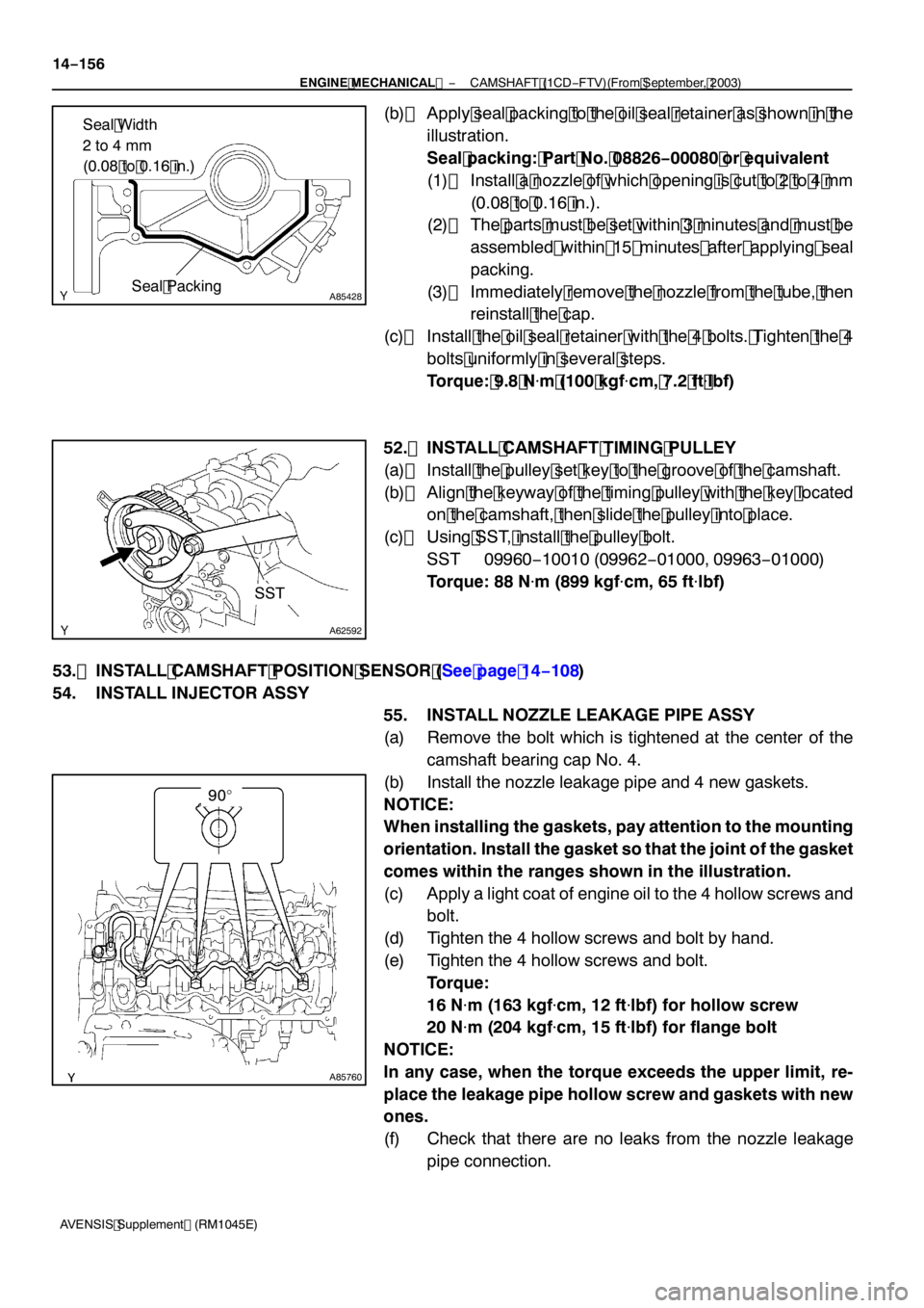
(b) Apply seal packing to the oil seal retainer as shown in the illustration.
Seal packing: Part No. 08826 −00080 or equivalent
(1) Install a nozzle of which opening is cut to 2 to 4 mm
(0.08 to 0.16 in.).
(2) The parts must be set within 3 minutes and must be
assembled within 15 minutes after applying seal
packing.
(3) Immediately remove the nozzle from the tube, then reinstall the cap.
(c) Install the oil seal retainer with the 4 bolts. Tighten the 4 bolts uniformly in several steps.
Torque: 9.8 N �m (100 kgf �cm, 7.2 ft �lbf)
52. INSTALL CAMSHAFT TIMING PULLEY
(a) Install the pulley set key to the groove of the camshaft.
(b) Align the keyway of the timing pulley with the key located on the camshaft, then slide the pulley into place.
(c) Using SST, install the pulley bolt. SST 09960 −10010 (09962 −01000, 09963 −01000)
Torque: 88 N �m (899 kgf �cm, 65 ft �lbf)
53. INSTALL CAMSHAFT POSITION SENSOR (See page 14 −108)
54. INSTALL INJECTOR ASSY 55. INSTALL NOZZLE LEAKAGE PIPE ASSY
(a) Remove the bolt which is tightened at the center of thecamshaft bearing cap No. 4.
(b) Install the nozzle leakage pipe and 4 new gaskets.
NOTICE:
When installing the gaskets, pay attention to the mounting
orientation. Install the gasket so that the joint of the gasket
comes within the ranges shown in the illustration.
(c) Apply a light coat of engine oil to the 4 hollow screws and bolt.
(d) Tighten the 4 hollow screws and bolt by hand.
(e) Tighten the 4 hollow screws and bolt. Torque:
16 N�m (163 kgf �cm, 12 ft �lbf) for hollow screw
20 N �m (204 kgf �cm, 15 ft �lbf) for flange bolt
NOTICE:
In any case, when the torque exceeds the upper limit, re-
place the leakage pipe hollow screw and gaskets with new
ones.
(f) Check that there are no leaks from the nozzle leakage pipe connection.
Page 4638 of 5135
A85618
N·m (kgf·cm, ft·lbf)
: Specified torque
zNon−reusable part
21 (214, 15)
Vacuum Pump Assy
zO−ring
20 (204, 15)
20 (204, 15)
Camshaft
No. 2 Camshaft
Set Key
Camshaft Timing Pulley
88 (899, 65)
Camshaft Carrier
zOil Seal
8.8 (90, 78 in.�lbf)Camshaft Oil Seal
Retainer
9.8 (100, 7.2)
Camshaft Position
Sensor
9.8 (100, 7.2)
Camshaft Bearing Cap
14−150
− ENGINE MECHANICALCAMSHAFT (1CD−FTV)(From September, 2003)
AVENSIS Supplement (RM1045E)
Page 4641 of 5135
A84302
A84303
A09605Turn
A61185
14−140
− ENGINE MECHANICALTIMING BELT (1CD−FTV)(From September, 2003)
AVENSIS Supplement (RM1045E)
17. REMOVE TIMING BELT NO.1 COVER
(a) Remove the 5 bolts and 5 seal washers, then remove the
timing belt cover.
18. REMOVE TIMING BELT GUIDE
19. REMOVE TRANSVERSE ENGINE ENGINE
MOUNTING BRACKET
(a) Remove the 6 bolts and engine mounting bracket.
20. SET NO. 1 CYLINDER TO TDC/COMPRESSION
(a) Using the crankshaft pulley bolt, align the dot mark of the
crankshaft timing gear with the TDC mark of the oil pump
by turning the crankshaft.
(b) Check that the timing mark of the camshaft timing pulley
is aligned with the joint of the cylinder head and cylinder
head cover.
Page 4642 of 5135

A87962
A09609
A09680
SST
A09611
A09606
− ENGINE MECHANICALTIMING BELT (1CD−FTV)(From September, 2003)
14−141
AVENSIS Supplement (RM1045E)
21. REMOVE TIMING CHAIN COVER PLATE
(a) Remove the bolt and timing chain cover plate.
22. REMOVE TIMING BELT
HINT:
If reusing the timing belt, draw an arrow on the belt which indi-
cates the engine revolution direction and put match marks on
the pulleys and belt before removing. This operation will be very
helpful when reinstalling the timing belt.
(a) Alternately loosen the 2 bolts to remove the timing belt
tensioner.
(b) Remove the timing belt.
23. SET NO. 1 CYLINDER TO TDC/COMPRESSION
(a) Using SST, set the pulleys of the camshaft and injection
pump so that each timing mark of the pulleys is aligned
with its timing mark on the cylinder head assembly and
water pump assembly.
SST 09960−10010 (09962−01000, 09963−01000)
(b) Using the crankshaft pulley bolt, align the dot mark of the
crankshaft timing gear with the TDC mark of the oil pump
by turning the crankshaft.
NOTICE:
Be very careful in turning the camshaft and crankshaft.
Since the valve head and piston head are sensitive, contact
of the piston head with the valve heads may damage them.
Page 4643 of 5135

A09612
1st
2nd 5th
3rd
4th 6th 7th
A09609
Timing Mark
Timing
Mark
Timing Mark
A09589
Hexagon
Wrench
(1.27 mm)
(A)
A09623
14−142
− ENGINE MECHANICALTIMING BELT (1CD−FTV)(From September, 2003)
AVENSIS Supplement (RM1045E)
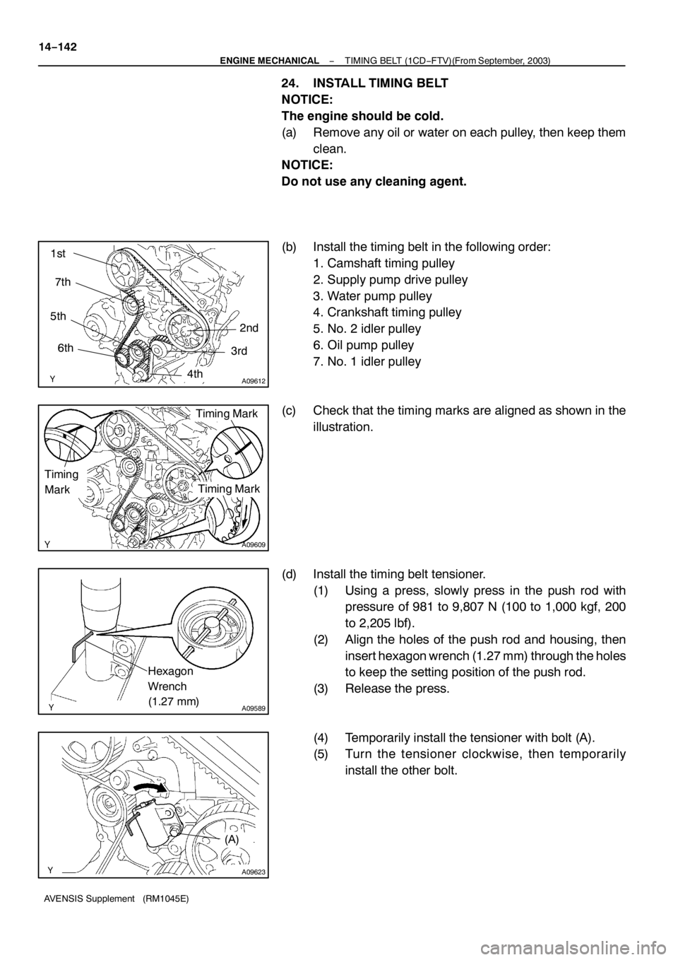
24. INSTALL TIMING BELT
NOTICE:
The engine should be cold.
(a) Remove any oil or water on each pulley, then keep them
clean.
NOTICE:
Do not use any cleaning agent.
(b) Install the timing belt in the following order:
1. Camshaft timing pulley
2. Supply pump drive pulley
3. Water pump pulley
4. Crankshaft timing pulley
5. No. 2 idler pulley
6. Oil pump pulley
7. No. 1 idler pulley
(c) Check that the timing marks are aligned as shown in the
illustration.
(d) Install the timing belt tensioner.
(1) Using a press, slowly press in the push rod with
pressure of 981 to 9,807 N (100 to 1,000 kgf, 200
to 2,205 lbf).
(2) Align the holes of the push rod and housing, then
insert hexagon wrench (1.27 mm) through the holes
to keep the setting position of the push rod.
(3) Release the press.
(4) Temporarily install the tensioner with bolt (A).
(5) Turn the tensioner clockwise, then temporarily
install the other bolt.
Page 4649 of 5135

141NG−01
A84393
(a)
(a)
(b)(b)
(a)
A84286
14 −108−
ENGINE MECHANICAL PARTIAL ENGINE ASSY (1CD −FTV)(From September,
2003)
AVENSIS Supplement (RM1045E)
REPLACEMENT
1. REMOVE FRONT WHEELS
2. REMOVE ENGINE UNDER COVER LH
3. REMOVE ENGINE UNDER COVER SUB −ASSY NO.1
4. REMOVE ENGINE UNDER COVER RH
5. REMOVE RADIATOR SUPPORT OPENING COVER
6. REMOVE ENGINE ROOM COVER SIDE
7. DRAIN ENGINE COOLANT (See page 16 −19)
8. DRAIN ENGINE OIL (See Pub No. RM1018E on page 17 −30)
9. DRAIN MANUAL TRANSAXLE OIL
Torque: 49 N �m (500 kgf �cm, 36 ft �lbf)
10. REMOVE ENGINE COVER SUB −ASSY NO.1
(a) Remove the 5 nuts, then remove the engine cover.
11. REMOVE BATTERY
12. REMOVE AIR CLEANER ASSY
(a) Disconnect the mass air flow meter connector.
(b) Remove the air cleaner cap together with the air cleaner hose.
(c) Remove the air cleaner filter element.
(d) Remove the 3 bolts and air cleaner case.
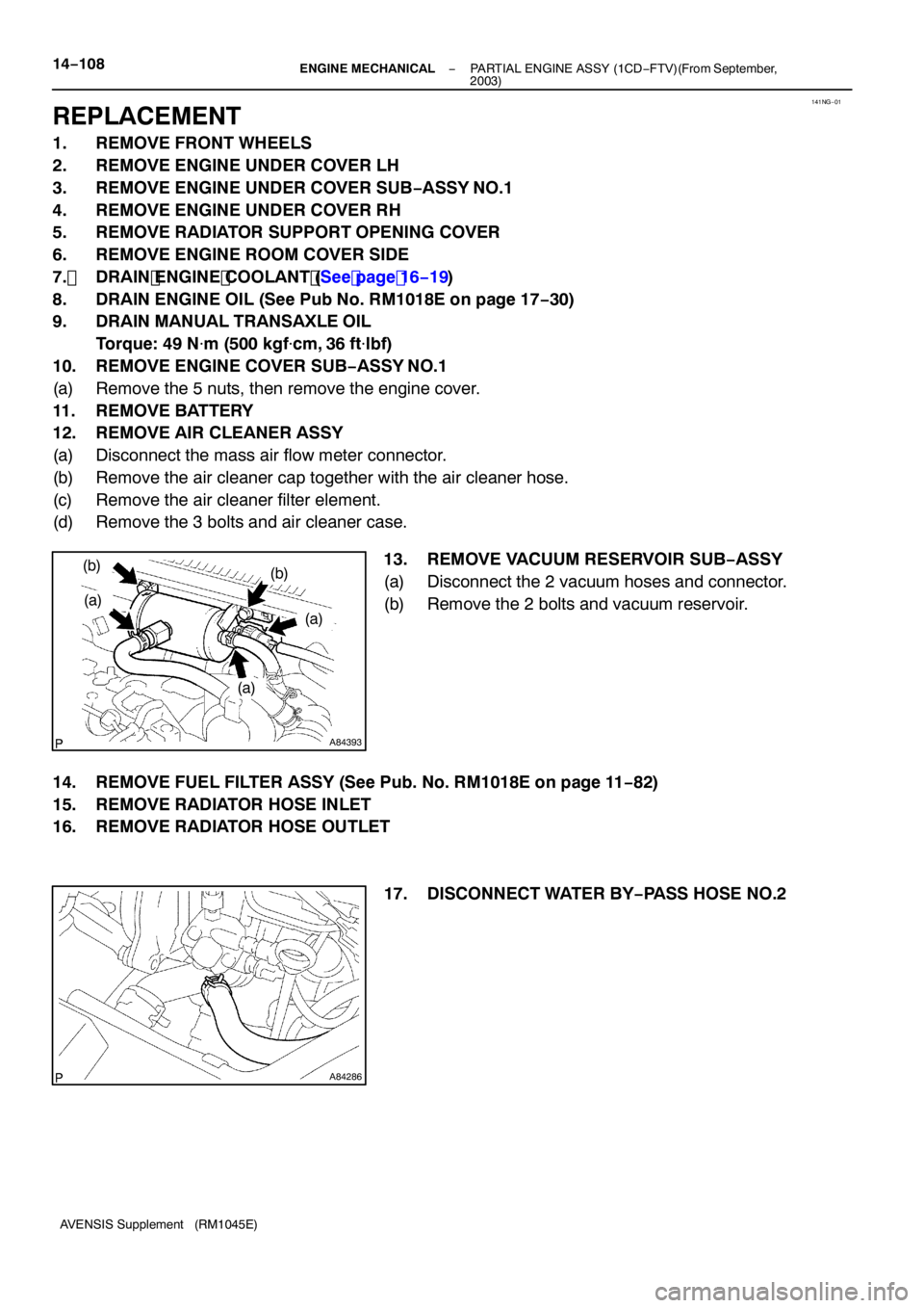
13. REMOVE VACUUM RESERVOIR SUB −ASSY
(a) Disconnect the 2 vacuum hoses and connector.
(b) Remove the 2 bolts and vacuum reservoir.
14. REMOVE FUEL FILTER ASSY (See Pub. No. RM1018E on page 11 −82)
15. REMOVE RADIATOR HOSE INLET
16. REMOVE RADIATOR HOSE OUTLET
17. DISCONNECT WATER BY−PASS HOSE NO.2