Page 4556 of 5135
A85747
N·m (kgf·cm, ft·lbf)
: Specified torque
zNon−reusable partzGasket
zGasket zGasket
20 (204, 15)
20 (204, 15)
20 (204, 15)
12 (122, 8.9)
60 (612, 44)
13 (135, 9.8)
36 (367, 27)
61 (622, 45)
56 (571, 41)
25 (255, 18)
Turbo Insulator No. 1
Exhaust Manifold Heat Insulator No. 2
Turbocharger Stay
Turbocharger Sub−assy
Turbo Oil Inlet Pipe
Sub−assy
Manifold Stay Manifold Stay No. 2
Exhaust Manifold
Converter Sub−assy Turbo Insulator No. 2
Turbo Water Pipe
Sub−assy No. 1
13 (135, 9.8)
56 (571, 41)
Turbo Water
Hose No. 2
Turbo Water
Hose No. 1
zGasket
12 (122, 8.9)
z
EGR Pipe Insulator
12 (122, 8.9)
x3x3
x2
x4
25 (255, 18)
Exhaust Gas Temperature
Sensor
Vacuum Transmitting
Pipe Sub−assy No. 2
30 (306, 22)
Vacuum Transmitting
Pipe Sub−assy No. 1
30 (306, 22)
x3
z
− INTAKETURBOCHARGER SUB−ASSY (1CD−FTV)(From
September, 2003)13−11
AVENSIS Supplement (RM1045E)
Page 4559 of 5135
(From
September, 2003)
AVENSIS Supplement (RM1045E)
TURBO CHARGER SYSTEM (1CD−FTV)(From September,
2003)
PRECAUTION
1.")
1302Y−04
A77119
A77120
A77121
13−4− INTAKETURBO CHARGER SYSTEM (1CD−FTV)(From
September, 2003)
AVENSIS Supplement (RM1045E)
TURBO CHARGER SYSTEM (1CD−FTV)(From September,
2003)
PRECAUTION
1. MAINTENANCE PRECAUTION
(a) Do not stop the engine immediately after pulling a trailer,
or after high speed or uphill driving. Let the engine idle for
20 to 120 seconds before turning the ignition switch to
OFF (according as the driving condition, the idling time
varies).
(b) Avoid quickly accelerating the pedal or increasing the en-
gine speed immediately after starting a cold engine.
(c) If the turbocharger is found defective, it must be replaced.
Also, inspect the source of the trouble including condi-
tions of the turbocharger that having been used. Repair
or replace the followings if necessary:
(1) Engine oil (level and quality)
(2) Oil lines leading to the turbocharger
(d) Pay due attention when removing and reinstalling the
turbocharger assembly. Do not drop, grasp, or give shock
to the easily−deformed assembly parts such as the actua-
tor or push rod when removing or reinstalling.
(e) Before removing, cover both the intake and exhaust ports
and the oil inlet to prevent dirt or foreign objects from be-
ing introduced.
(f) If replacing the turbocharger, check the oil pipe for depos-
its. If necessary, replace the oil pipe, too.
(g) Thoroughly remove old gasket sticking to the lubrication
oil pipe flange and turbocharger oil flange.
(h) If replacing the bolt(s) or nut(s), Toyota genuine parts
must be used to prevent breakage or deformation.
(i) If replacing the turbocharger, put 20 cm
3(1.2 cu in.) of
fresh oil into the turbocharger oil inlet hole, then turn the
turbine wheel by hand to spread oil to the bearing.
(j) If overhauling or replacing the engine, cut the fuel supply
after reassembling and crank the engine for 30 seconds
to feed oil throughout the engine. Run the engine at idle
for 60 seconds.
Page 4574 of 5135
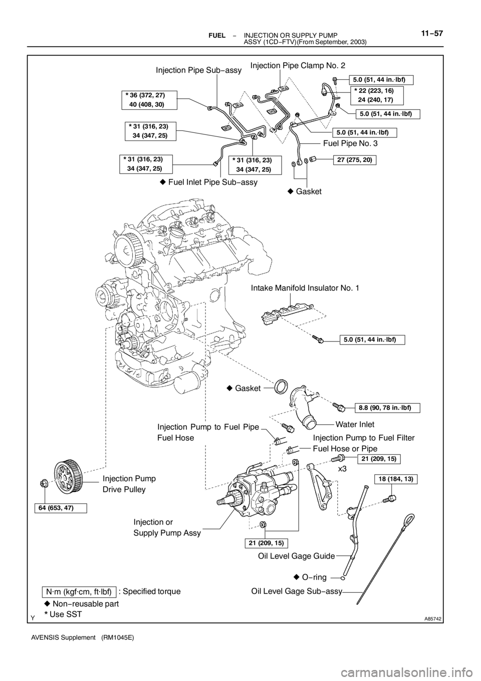
A85742
5.0 (51, 44 in.�lbf)
* 36 (372, 27)
40 (408, 30)
* 31 (316, 23)
34 (347, 25)
* 31 (316, 23)
34 (347, 25)
Injection Pipe Clamp No. 2
Injection Pipe Sub−assy
zFuel Inlet Pipe Sub−assy
64 (653, 47)
Injection Pump
Drive Pulley
zO−ring Oil Level Gage Guide
: Specified torqueN·m (kgf·cm, ft·lbf)
* Use SST
18 (184, 13)
Oil Level Gage Sub−assy Injection or
Supply Pump Assy
21 (209, 15)
21 (209, 15)
Water Inlet
8.8 (90, 78 in.�lbf)
zGasket
5.0 (51, 44 in.�lbf)
Intake Manifold Insulator No. 1
Injection Pump to Fuel Filter
Fuel Hose or Pipe
Injection Pump to Fuel Pipe
Fuel Hose
Fuel Pipe No. 3
zGasket
27 (275, 20)
5.0 (51, 44 in.�lbf)
x3
zNon−reusable part
5.0 (51, 44 in.�lbf)
* 22 (223, 16)
24 (240, 17)
* 31 (316, 23)
34 (347, 25)
− FUELINJECTION OR SUPPLY PUMP
ASSY (1CD−FTV)(From September, 2003)11−57
AVENSIS Supplement (RM1045E)
Page 4578 of 5135
(From September, 2003)
11−49
AVENSIS Supplement (RM1045E)
19. INSTALL INJECTOR ASSY
(a) Install the 4 new nozzle sea")
A79187
O−ring Back−up Ring
A92435
A85760
90_
− FUELINJECTOR ASSY (1CD−FTV)(From September, 2003)
11−49
AVENSIS Supplement (RM1045E)
19. INSTALL INJECTOR ASSY
(a) Install the 4 new nozzle seats to the cylinder head.
(b) Install new back−up rings and O−rings to each injector.
(c) Apply a light coat of engine oil to the O−rings on each in-
jector.
(d) Install the injector to the cylinder head.
NOTICE:
Fit the injectors to the nozzle seat.
(e) Install the nozzle holder clamp as shown in the illustration.
Tighten the camshaft bearing cap bolt by hand to fix the
nozzle holder clamp.
NOTICE:
SPay attention to the mounting orientation of the wash-
er.
SWhen temporarily attaching the nozzle holder clamp
and mounting bolt, be careful not to orient them at an
angle.
HINT:
Apply a light coat of engine oil to the threads of the nozzle hold-
er clamp bolts.
(f) Install the injection pipe No. 1, No. 2, No. 3 and No. 4, then
tighten the nuts by hand.
(g) Install new 4 gaskets and the leakage pipe No. 1. Tighten
the 4 hollow screws by hand.
(h) Tighten the 4 nozzle holder clamp bolts.
Torque: 27 N�m (270 kgf�cm, 20 ft�lbf)
(i) Remove the 4 injection pipes.
20. INSTALL NOZZLE LEAKAGE PIPE ASSY
(a) Install the nozzle leakage pipe and 4 new gaskets.
NOTICE:
When installing the gaskets, pay attention to the mounting
orientation. Install the gasket so that the joint of the gasket
comes within the range shown in the illustration.
(b) Apply a light coat of engine oil to the 4 hollow screws and
the bolt.
Page 4594 of 5135

11−17
AVENSIS Supple")
A80297
E−ring
Fuel Injector
Back−up Ring No. 3
Fuel Injector
Back−up Ring No. 2
Fuel Injector
Back−up Ring No. 1O−ring
A79592
5_
− FUELFUEL INJECTOR ASSY (2AZ−FSE)
11−17
AVENSIS Supplement (RM1045E)
21. INSTALL FUEL INJECTOR ASSY
(a) Install new fuel injector back−up ring No. 1, No. 2, No. 3,
a new O−ring and a new E−ring to each fuel injector.
NOTICE:
SThere is a draft angle inside the back−up ring No. 1
and No. 2. Put the draft angle downward when instal-
ling those rings to the fuel injector.
SThe back−up ring No. 1 and No. 2 have a diagonal slit.
Pay attention to the splice of the slits after installing
them.
SAfter Installation of these 5 rings to the fuel injector,
check that there are no damages and foreign objects
on them.
(b) Apply a light coat of spindle oil or gasoline to the O−ring
on the fuel injector and the mounting hole on the fuel de-
livery pipe.
(c) Install the fuel injector to the fuel delivery pipe as shown
in the illustration.
NOTICE:
SBe careful not to damage the sealing surface of the
fuel delivery pipe when installing the injector.
SCheck that there are no damages and foreign objects
in the fuel injector mounting hole of the fuel delivery
pipe sub−assy.
SIn order to avoid any damage, be sure to apply fuel to
both the O−ring and the mounting hole before instal-
ling the fuel injector to the fuel delivery pipe.
Page 4597 of 5135
11−20
−
FUEL FUEL INJECTOR ASSY (2AZ −FSE)
AVENSIS Supplement (RM1045E)
36. ADD ENGINE COOLANT (see page 16 −7)
37. CHECK FOR ENGINE COOLANT LEAKS (See page 16 −1)
38. CHECK FOR FUEL LEAKS (See page 11 −4)
39. CHECK FOR ENGINE OIL LEAKS
40. INSTALL ENGINE COVER SUB −ASSY NO.1 (See page 10 −8)
41. INSTALL ENGINE ROOM COVER SIDE
42. INSTALL RADIATOR SUPPORT OPENING COVER
Page 4598 of 5135

11−7
AVENSIS Supplement (RM1045E)
INSPECTION
1. INSPECT FUEL INJECTOR ASSY
NOTICE:
This insp")
1111 2−01
A84684
Ohmmeter
A84687
Ohmmeter
A88285
Ohmmeter
A88300Battery
− FUELFUEL SYSTEM (2AZ−FSE)
11−7
AVENSIS Supplement (RM1045E)
INSPECTION
1. INSPECT FUEL INJECTOR ASSY
NOTICE:
This inspection aims at inspecting the fuel injectors for
open or short, because the fuel injectors of this vehicle are
high−pressure type and do not allow to inspect fuel injec-
tion volume.
(a) Inspect the resistance.
(1) Using an ohmmeter, measure the resistance be-
tween the terminals.
Standard:
Tester ConnectionSpecified Condition
1−22.55 to 2.85�at 20_C (68_F)
If the resistance is not as specified, replace the fuel injector.
2. INSPECT FUEL PUMP ASSY
(a) Inspect the resistance.
(1) Using an ohmmeter, measure the resistance be-
tween the terminals.
Standard:
Tester ConnectionSpecified Condition
1−21.19 to 1.39�at 20_C (68_F)
If the resistance is not as specified, replace the fuel pump.
3. INSPECT FUEL PUMP ASSY
(a) Inspect the resistance.
(1) Using an ohmmeter, measure the resistance be-
tween the terminals.
Standard:
Tester ConnectionSpecified Condition
4−50.2 to 3.0�at 20_C (68_F)
If the resistance is not as specified, replace the fuel pump.
(b) Check the operation.
(1) Apply battery voltage across the terminals. Check
that the fuel pump operates.
NOTICE:
SThese tests must be performed quickly (within 10 se-
conds) to prevent burnout of the coil.
SKeep fuel pump as far away from the battery as pos-
sible.
SAlways do the switching at the battery side.
If the operate is not as specified, replace the fuel pump.
Page 4613 of 5135
−
ENGINE CONTROL SYSTEM KNOCK SENSOR (2AZ−FSE)
10 −17
AVENSIS Supplement (RM1045E)
25. INSTALL FUEL PUMP ASSY (See page 11 −24)
26. INSTALL FUEL PIPE SUB −ASSY NO.1 (See page 11 −24)
SST 09023 −12900
27. INSTALL FUEL HOSE
28. INSTALL FUEL TUBE SUB −ASSY (See page 11 −24)
SST 09617 −24011
29. INSTALL THROTTLE BODY ASSY (See page 10 −8)
30. INSTALL AIR CLEANER CAP SUB −ASSY (See page 10 −8)
31. CONNECT ENGINE WIRE NO.3 (BATTERY NEGATIVE TERMINAL) Torque: 5.4 N �m (55 kgf �cm, 48 in. �lbf)
32. ADD ENGINE COOLANT (See page 16 −7)
33. CHECK FOR ENGINE COOLANT LEAKS (See page 16 −1)
34. CHECK FOR FUEL LEAKS (See page 11 −4)
35. CHECK FOR ENGINE OIL LEAKS
36. INSTALL ENGINE COVER SUB −ASSY NO.1 ( See page 10 −8)
37. INSTALL ENGINE ROOM COVER SIDE
38. INSTALL RADIATOR SUPPORT OPENING COVER

: Specified torque
zNon−reusable partzGasket
zGasket zGasket
20 (204, 15)
20 (204, 15)
20 (204, 15)
12 (122, 8.9)
60 (612, 44)
13 (135, 9.8)
36 (367, 27)
61 (622, 45)")

AVENSIS Supplement (RM1045E)
36. ADD ENGINE COOLANT (see page 16 −7)
37. CHECK FOR ENGINE COOLANT LEAKS (See page 16 −1)
38. CHECK FOR FUEL LEAKS")

10 −17
AVENSIS Supplement (RM1045E)
25. INSTALL FUEL PUMP ASSY (See page 11 −24)
26. INSTALL FUEL PIPE SUB −ASSY NO.1 (See page 11 −24)
SST")