Page 4 of 687
Downloaded from www.Manualslib.com manuals search engine TABLE OF CONTENTS
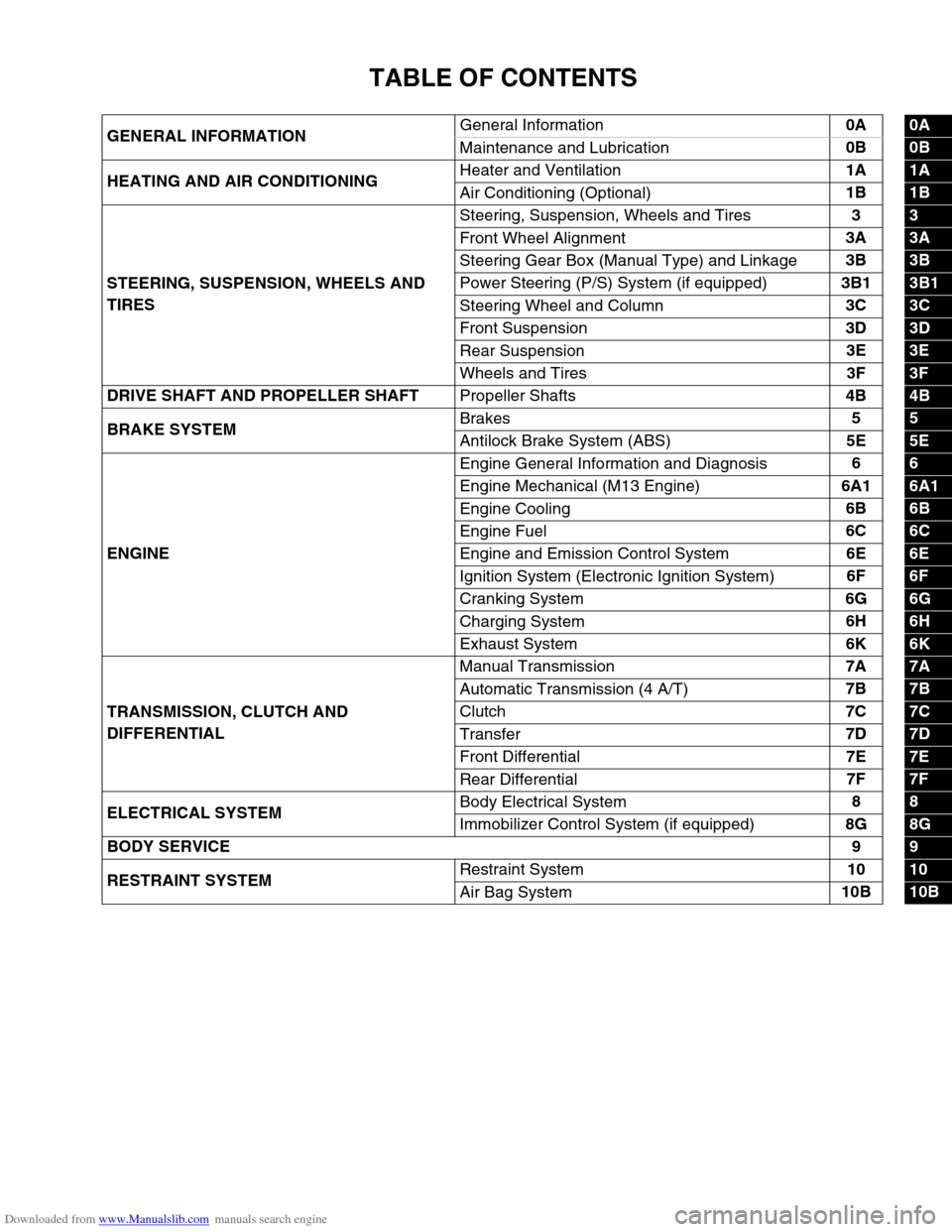
GENERAL INFORMATIONGeneral Information0A0A
Maintenance and Lubrication0B
0B
HEATING AND AIR CONDITIONINGHeater and Ventilation1A
1A
Air Conditioning (Optional)1B
1B
STEERING, SUSPENSION, WHEELS AND
TIRESSteering, Suspension, Wheels and Tires3
3
Front Wheel Alignment3A
3A
Steering Gear Box (Manual Type) and Linkage3B
3B
Power Steering (P/S) System (if equipped)3B1
3B1
Steering Wheel and Column3C
3C
Front Suspension3D
3D
Rear Suspension3E
3E
Wheels and Tires3F
3F
DRIVE SHAFT AND PROPELLER SHAFT
Propeller Shafts4B
4B
BRAKE SYSTEMBrakes5
5
Antilock Brake System (ABS)5E
5E
ENGINEEngine General Information and Diagnosis6
6
Engine Mechanical (M13 Engine)6A1
6A1
Engine Cooling6B
6B
Engine Fuel6C
6C
Engine and Emission Control System6E
6E
Ignition System (Electronic Ignition System)6F
6F
Cranking System6G
6G
Charging System6H
6H
Exhaust System6K
6K
TRANSMISSION, CLUTCH AND
DIFFERENTIALManual Transmission7A
7A
Automatic Transmission (4 A/T)7B
7B
Clutch7C
7C
Transfer7D
7D
Front Differential7E
7E
Rear Differential7F
7F
ELECTRICAL SYSTEMBody Electrical System8
8
Immobilizer Control System (if equipped)8G
8G
BODY SERVICE9
9
RESTRAINT SYSTEMRestraint System10
10
Air Bag System10B
10B
Page 10 of 687
Downloaded from www.Manualslib.com manuals search engine GENERAL INFORMATION 0A-5
WARNING:
SDM
During service procedures, be very careful when handling a Sensing and Diagnostic Module (SDM).
Never strike or jar the SDM.
Never power up the air bag system when the SDM is not rigidly attached to the vehicle. All SDM and
mounting bracket fasteners must be carefully torqued and the arrow must be pointing toward the
front of the vehicle to ensure proper operation of the air bag system.
The SDM could be activated when powered while not rigidly attached to the vehicle which could
cause deployment and result in personal injury.
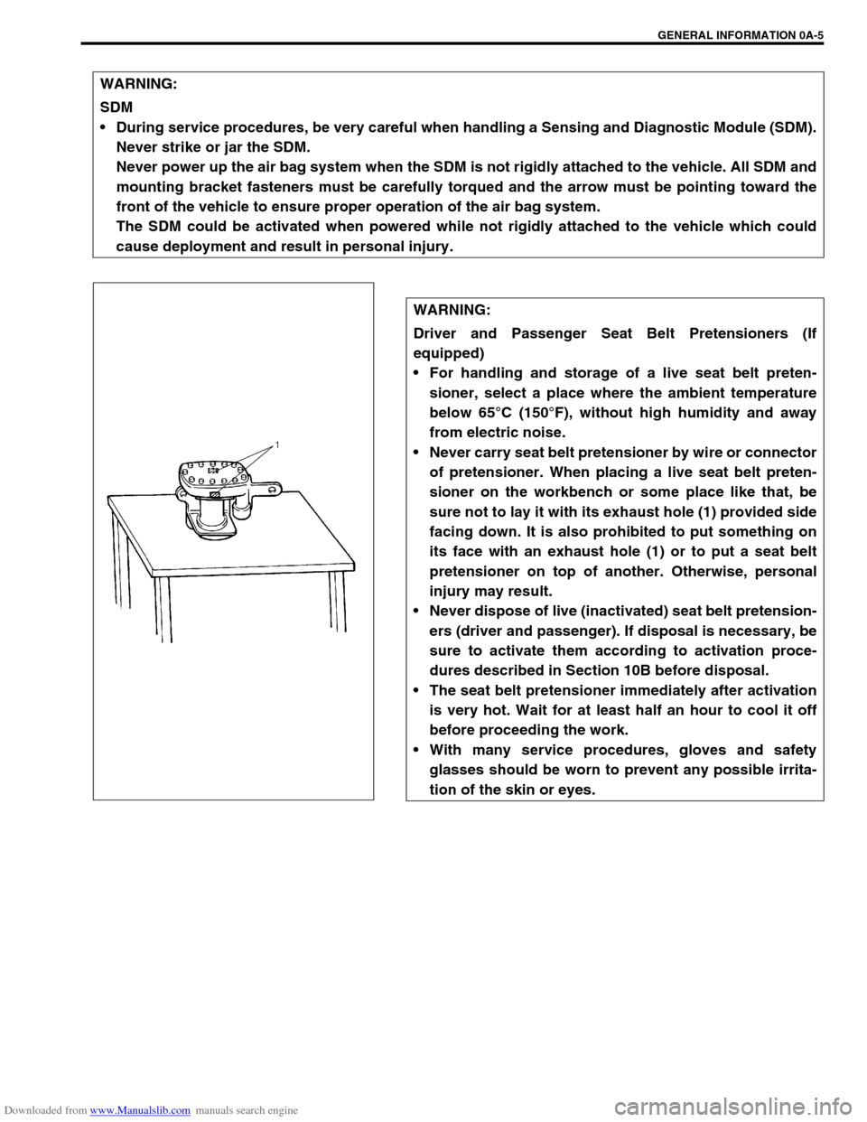
WARNING:
Driver and Passenger Seat Belt Pretensioners (If
equipped)
For handling and storage of a live seat belt preten-
sioner, select a place where the ambient temperature
below 65°C (150°F), without high humidity and away
from electric noise.
Never carry seat belt pretensioner by wire or connector
of pretensioner. When placing a live seat belt preten-
sioner on the workbench or some place like that, be
sure not to lay it with its exhaust hole (1) provided side
facing down. It is also prohibited to put something on
its face with an exhaust hole (1) or to put a seat belt
pretensioner on top of another. Otherwise, personal
injury may result.
Never dispose of live (inactivated) seat belt pretension-
ers (driver and passenger). If disposal is necessary, be
sure to activate them according to activation proce-
dures described in Section 10B before disposal.
The seat belt pretensioner immediately after activation
is very hot. Wait for at least half an hour to cool it off
before proceeding the work.
With many service procedures, gloves and safety
glasses should be worn to prevent any possible irrita-
tion of the skin or eyes.
Page 24 of 687
Downloaded from www.Manualslib.com manuals search engine GENERAL INFORMATION 0A-19
Vehicle Lifting Points
When Using Frame Contact Hoist
WARNING:
Before applying hoist to underbody, always take vehicle balance throughout service into consider-
ation. Vehicle balance on hoist may change depending on what part to be removed.
Before lifting up the vehicle, check to be sure that end of hoist arm is not in contact with brake pipe,
fuel pipe, bracket or any other part.
When using frame contact hoist, apply hoist as shown (right and left at the same position). Lift up
the vehicle till 4 tires are a little off the ground and make sure that the vehicle will not fall off by try-
ing to move vehicle body in both ways. Work can be started only after this confirmation.
Make absolutely sure to lock hoist after vehicle is hoisted up.
1. Front lifting point
2. Rear lifting point
3. Front
Page 25 of 687
Downloaded from www.Manualslib.com manuals search engine 0A-20 GENERAL INFORMATION
When Using Floor Jack
In raising front or rear vehicle end off the floor by jacking, be sure
to put the jack against the center portion of the front axle housing
(1) or rear axle housing (2).
To perform service with either front or rear vehicle end jacked up,
be sure to place safety stands (1) under chassis frame so that
body is securely supported. And then check to ensure that chas-
sis frame does not slide on safety stands (1) and the vehicle is
held stable for safety’s sake. WARNING:
If the vehicle to be jacked up only at the front or rear end,
be sure to block the wheels on ground in order to ensure
safety.
After the vehicle is jacked up, be sure to support it on
stands. It is extremely dangerous to do any work on the
vehicle raised on jack alone.
CAUTION:
Never apply jack against suspension parts (i.e., stabi-
lizer, etc.) or vehicle floor, or it may get deformed.
[A]: Front
[B]: Rear
Page 42 of 687
Downloaded from www.Manualslib.com manuals search engine MAINTENANCE AND LUBRICATION 0B-11
PCV (Positive Crankcase Ventilation) Valve
INSPECTION
Check crankcase ventilation hose and PCV hose for leaks, cracks
or clog, and PCV valve for stick or clog. Refer to “PCV System” of
Section 6E for PCV valve checking procedure.
Fuel Evaporative Emission Control System
INSPECTION
1) Visually inspect hoses for cracks, damage, or excessive
bends. Inspect all clamps for damage and proper position.
2) Check EVAP canister for operation and clog, referring to
“Evaporative Emission (EVAP) Control System” in Section
6E.
If a malfunction is found, repair or replace.
Chassis and Body
Clutch
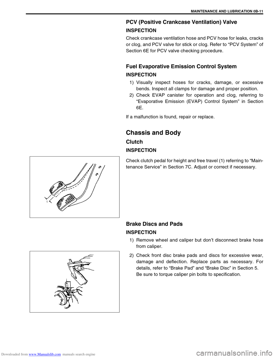
INSPECTION
Check clutch pedal for height and free travel (1) referring to “Main-
tenance Service” in Section 7C. Adjust or correct if necessary.
Brake Discs and Pads
INSPECTION
1) Remove wheel and caliper but don’t disconnect brake hose
from caliper.
2) Check front disc brake pads and discs for excessive wear,
damage and deflection. Replace parts as necessary. For
details, refer to “Brake Pad” and “Brake Disc” in Section 5.
Be sure to torque caliper pin bolts to specification.
Page 45 of 687
Downloaded from www.Manualslib.com manuals search engine 0B-14 MAINTENANCE AND LUBRICATION
3) Rotate tires.
For details, refer to “Tire Rotation” in Section 3F.
WHEEL DISCS INSPECTION
Inspect each wheel disc for dents, distortion and cracks. A disc in
badly damaged condition must be replaced.
WHEEL BEARING INSPECTION
1) Check front wheel bearing for wear, damage, abnormal
noise or rattles. For details, refer to “Wheel Disc, Nut and
Bearing Check” in Section 3D.
2) Check rear wheel bearing for wear, damage, abnormal noise
or rattles. For details, refer to “Wheel Disc, Nut and Bearing
Check” in Section 3E.
Suspension System
INSPECTION
Check suspension bolts and nuts for tightness and retighten them
as necessary.
Repair or replace defective parts, if any.
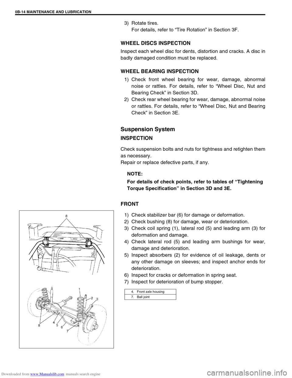
FRONT
1) Check stabilizer bar (6) for damage or deformation.
2) Check bushing (8) for damage, wear or deterioration.
3) Check coil spring (1), lateral rod (5) and leading arm (3) for
deformation and damage.
4) Check lateral rod (5) and leading arm bushings for wear,
damage and deterioration.
5) Inspect absorbers (2) for evidence of oil leakage, dents or
any other damage on sleeves; and inspect anchor ends for
deterioration.
6) Inspect for cracks or deformation in spring seat.
7) Inspect for deterioration of bump stopper.NOTE:
For details of check points, refer to tables of “Tightening
Torque Specification” in Section 3D and 3E.
4. Front axle housing
7. Ball joint
Page 46 of 687
Downloaded from www.Manualslib.com manuals search engine MAINTENANCE AND LUBRICATION 0B-15
REAR
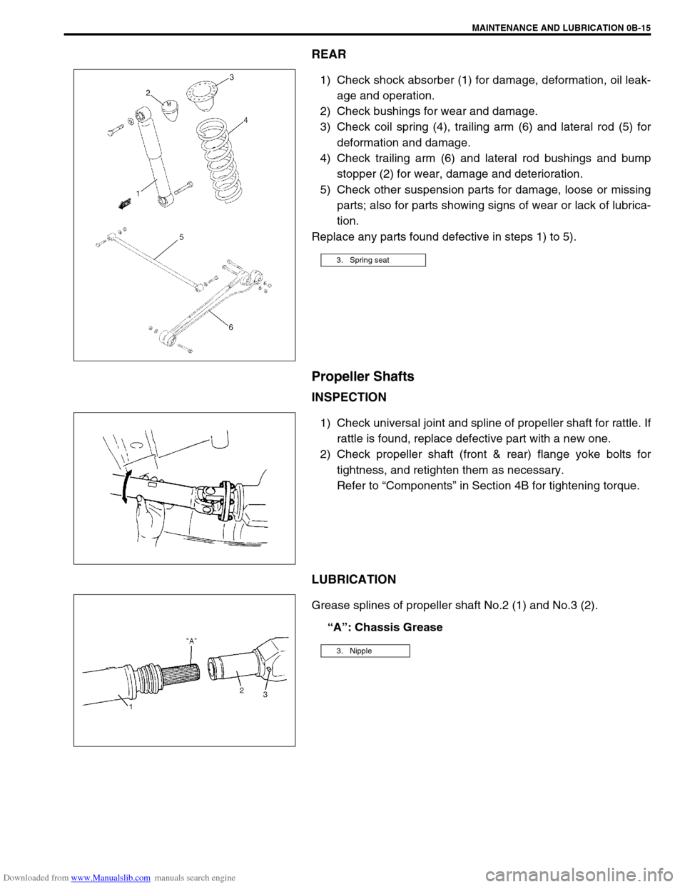
1) Check shock absorber (1) for damage, deformation, oil leak-
age and operation.
2) Check bushings for wear and damage.
3) Check coil spring (4), trailing arm (6) and lateral rod (5) for
deformation and damage.
4) Check trailing arm (6) and lateral rod bushings and bump
stopper (2) for wear, damage and deterioration.
5) Check other suspension parts for damage, loose or missing
parts; also for parts showing signs of wear or lack of lubrica-
tion.
Replace any parts found defective in steps 1) to 5).
Propeller Shafts
INSPECTION
1) Check universal joint and spline of propeller shaft for rattle. If
rattle is found, replace defective part with a new one.
2) Check propeller shaft (front & rear) flange yoke bolts for
tightness, and retighten them as necessary.
Refer to “Components” in Section 4B for tightening torque.
LUBRICATION
Grease splines of propeller shaft No.2 (1) and No.3 (2).
“A”: Chassis Grease
3. Spring seat
3. Nipple
Page 48 of 687
Downloaded from www.Manualslib.com manuals search engine MAINTENANCE AND LUBRICATION 0B-17
FLUID COOLER HOSE CHANGE
Replace inlet and outlet hoses of cooler hose and their clamps.
For replacement procedure, refer to “Oil Cooler Hoses” in Section
7B.
Transfer and Differential Oil
INSPECTION
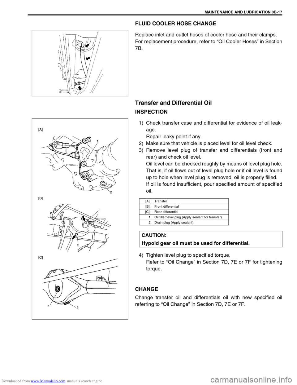
1) Check transfer case and differential for evidence of oil leak-
age.
Repair leaky point if any.
2) Make sure that vehicle is placed level for oil level check.
3) Remove level plug of transfer and differentials (front and
rear) and check oil level.
Oil level can be checked roughly by means of level plug hole.
That is, if oil flows out of level plug hole or if oil level is found
up to hole when level plug is removed, oil is properly filled.
If oil is found insufficient, pour specified amount of specified
oil.
4) Tighten level plug to specified torque.
Refer to “Oil Change” in Section 7D, 7E or 7F for tightening
torque.
CHANGE
Change transfer oil and differentials oil with new specified oil
referring to “Oil Change” in Section 7D, 7E or 7F.
[A] : Transfer
[B] : Front differential
[C] : Rear differential
1. Oil filler/level plug (Apply sealant for transfer)
2. Drain plug (Apply sealant)
CAUTION:
Hypoid gear oil must be used for differential.