2005 SUZUKI JIMNY Seats
[x] Cancel search: SeatsPage 12 of 687

Downloaded from www.Manualslib.com manuals search engine GENERAL INFORMATION 0A-7
General Precautions
The WARNING and CAUTION below describe some general precautions that you should observe when servic-
ing a vehicle. These general precautions apply to many of the service procedures described in this manual, and
they will not necessarily be repeated with each procedure to which they apply.
Before starting any service work, cover fenders, seats
and any other parts that are likely to get scratched or
stained during servicing. Also, be aware that what you
wear (e.g, buttons) may cause damage to the vehicle’s
finish.
When performing service to electrical parts that does
not require use of battery power, disconnect the nega-
tive cable of the battery. WARNING:
Whenever raising a vehicle for service, be sure to follow the instructions under “Vehicle Lifting
Points” in this section.
When it is necessary to do service work with the engine running, make sure that the parking brake
is set fully and the transmission is in Neutral (for manual transmission vehicles) or Park (for auto-
matic transmission vehicles), Keep hands, hair, clothing, tools, etc. away from the fan and belts
when the engine is running.
When it is necessary to run the engine indoors, make sure that the exhaust gas is forced outdoors.
Do not perform service work in areas where combustible materials can come in contact with a hot
exhaust system. When working with toxic or flammable materials (such as gasoline and refriger-
ant), make sure that the area you work in is well-ventilated.
To avoid getting burned, keep away from hot metal parts such as the radiator, exhaust manifold,
tailpipe, muffler, etc.
New and used engine oil can be hazardous. Children and pets may be harmed by swallowing new or
used oil. Keep new and used oil and used engine oil filters away from children and pets.
Continuous contact with used engine oil has been found to cause [skin] cancer in laboratory ani-
mals. Brief contact with used oil may irritate skin. To minimize your exposure to used engine oil,
wear a long-sleeve shirt and moisture-proof gloves (such as dish washing gloves) when changing
engine oil. If engine oil contacts your skin, wash thoroughly with soap and water. Launder any
clothing or rags if wet with oil, recycle or properly dispose of used oil and filters.
Make sure the bonnet is fully closed and latched before driving. If it is not, it can fly up unexpectedly
during driving, obstructing your view and resulting in an accident.
Page 51 of 687

Downloaded from www.Manualslib.com manuals search engine 0B-20 MAINTENANCE AND LUBRICATION
Final Inspection
SEATS
Check that seat slides smoothly and locks securely at any position. Also check that reclining mechanism of front
seat back allows it to be locked at any angle.
SEAT BELT
Inspect belt system including webbing, buckles, latch plates, retractors and anchors for damage or wear.
If “REPLACE BELT” label on front seat belt is visible, replace belt. Check that seat belt is securely locked.
BATTERY ELECTROLYTE LEVEL CHECK
Check that the electrolyte level of all battery cells is between the upper and lower level lines on the case. If bat-
tery is equipped with built-in indicator, check battery condition by the indicator.
ACCELERATOR PEDAL OPERATION
Check that pedal operates smoothly without getting caught or interfered by any other part.
ENGINE START
Check engine start for readiness.
On automatic transmission vehicles, try to start the engine in each select lever position. The starting motor
should crank only in “P” (Park) or “N” (Neutral).
On manual transmission vehicles, place the shift lever in “Neutral,” depress clutch pedal fully any try to start.
EXHAUST SYSTEM CHECK
Check for leakage, cracks or loose supports.
CLUTCH (FOR MANUAL TRANSMISSION)
Check for the following.
Clutch is completely released when depressing clutch pedal,
No slipping clutch occurs when releasing pedal and accelerating.
Clutch itself is free from any abnormal condition. WARNING:
When carrying out road tests, select a safe place where no man or no running vehicle is seen so as to
prevent any accident.
WARNING:
Before performing the following check, be sure to have enough room around the vehicle. Then, firmly
apply both the parking brake and the regular brakes. Do not use the accelerator pedal. If the engine
starts, be ready to turn off the ignition promptly. Take these precautions because the vehicle could
move without warning and possibly cause personal injury or property damage.
Page 90 of 687

Downloaded from www.Manualslib.com manuals search engine AIR CONDITIONING (OPTIONAL) 1B-29
On-Vehicle Service
Service Precaution
When servicing air conditioning system, note the following instructions.
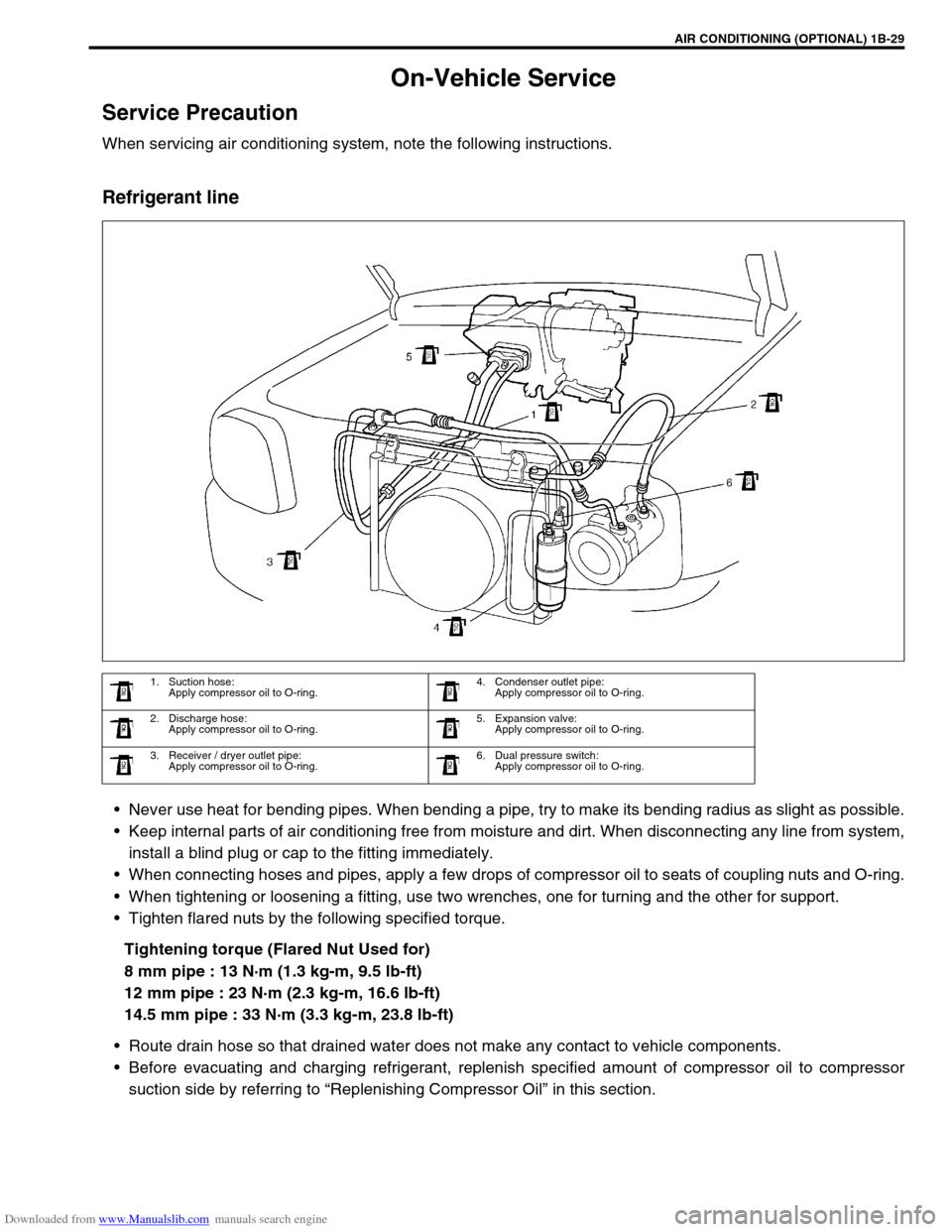
Refrigerant line
Never use heat for bending pipes. When bending a pipe, try to make its bending radius as slight as possible.
Keep internal parts of air conditioning free from moisture and dirt. When disconnecting any line from system,
install a blind plug or cap to the fitting immediately.
When connecting hoses and pipes, apply a few drops of compressor oil to seats of coupling nuts and O-ring.
When tightening or loosening a fitting, use two wrenches, one for turning and the other for support.
Tighten flared nuts by the following specified torque.
Tightening torque (Flared Nut Used for)
8 mm pipe : 13 N·m (1.3 kg-m, 9.5 lb-ft)
12 mm pipe : 23 N·m (2.3 kg-m, 16.6 lb-ft)
14.5 mm pipe : 33 N·m (3.3 kg-m, 23.8 lb-ft)
Route drain hose so that drained water does not make any contact to vehicle components.
Before evacuating and charging refrigerant, replenish specified amount of compressor oil to compressor
suction side by referring to “Replenishing Compressor Oil” in this section.
1. Suction hose:
Apply compressor oil to O-ring.4. Condenser outlet pipe:
Apply compressor oil to O-ring.
2. Discharge hose:
Apply compressor oil to O-ring.5. Expansion valve:
Apply compressor oil to O-ring.
3. Receiver / dryer outlet pipe:
Apply compressor oil to O-ring.6. Dual pressure switch:
Apply compressor oil to O-ring.
Page 252 of 687

Downloaded from www.Manualslib.com manuals search engine WHEELS AND TIRES 3F-9
Tire
Mounting and demounting
Use tire changing machine to mount or demount tires. Follow equipment manufacturer’s instructions. Do not use
hand tools or tire irons alone to change tires as they may damage tire beads or wheel rim.
Rim bead seats should be cleaned with wire brush or coarse steel wool to remove lubricants, old rubber and
light rust. Before mounting or demounting tire, bead area should be well lubricated with approved tire lubricant.
After mounting, inflate to 240 kPa (35 psi) so that beads are completely seated. Then adjust pressure to speci-
fied shown on tire placard.
Install valve core and inflate to proper pressure.
Repair
There are many different materials and techniques on the market to repair tires. As not all of these work on all
types of tires, tire manufacturers have published detailed instructions on how and when to repair tires. These
instructions can be obtained from the tire manufacturer.WARNING:
Do not stand over tire when inflating. Bead may break when bead snaps over rim’s safety hump and
cause serious personal injury.
Do not exceed 240 kPa (35 psi) pressure when inflating. If 240 kPa (35 psi) pressure will not seat
beads, deflate, re-lubricate and reinflate. Over inflation may cause bead to break and cause serious
personal injury.
Page 536 of 687

Downloaded from www.Manualslib.com manuals search engine ENGINE MECHANICAL (M13 ENGINE) 6A1-55
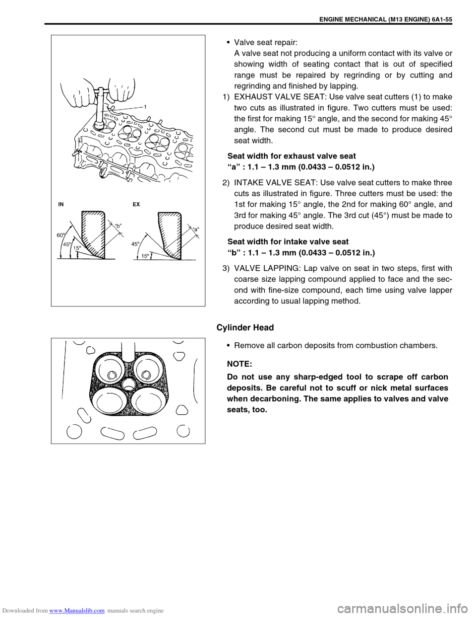
Valve seat repair:
A valve seat not producing a uniform contact with its valve or
showing width of seating contact that is out of specified
range must be repaired by regrinding or by cutting and
regrinding and finished by lapping.
1) EXHAUST VALVE SEAT: Use valve seat cutters (1) to make
two cuts as illustrated in figure. Two cutters must be used:
the first for making 15° angle, and the second for making 45°
angle. The second cut must be made to produce desired
seat width.
Seat width for exhaust valve seat
“a” : 1.1 – 1.3 mm (0.0433 – 0.0512 in.)
2) INTAKE VALVE SEAT: Use valve seat cutters to make three
cuts as illustrated in figure. Three cutters must be used: the
1st for making 15° angle, the 2nd for making 60° angle, and
3rd for making 45° angle. The 3rd cut (45°) must be made to
produce desired seat width.
Seat width for intake valve seat
“b” : 1.1 – 1.3 mm (0.0433 – 0.0512 in.)
3) VALVE LAPPING: Lap valve on seat in two steps, first with
coarse size lapping compound applied to face and the sec-
ond with fine-size compound, each time using valve lapper
according to usual lapping method.
Cylinder Head
Remove all carbon deposits from combustion chambers.
NOTE:
Do not use any sharp-edged tool to scrape off carbon
deposits. Be careful not to scuff or nick metal surfaces
when decarboning. The same applies to valves and valve
seats, too.