2005 SUZUKI JIMNY throttle body
[x] Cancel search: throttle bodyPage 27 of 687

Downloaded from www.Manualslib.com manuals search engine 0A-22 GENERAL INFORMATION
LLH
LSPVLeft Hand
Load Sensing Proportioning Valve
TTBI
TCC
TCM
TP Sensor
TVV
TWC
2WDThrottle Body Fuel Injection
(Single-Point Fuel Injection, SPI)
Torque Converter Clutch
Transmission Control Module
(A/T Controller, A/T Control Mod-
ule)
Throttle Position Sensor
Thermal Vacuum Valve
(Thermal Vacuum Switching Valve,
TVSV, Bimetal Vacuum Switching
Valve, BVSV)
Three Way Catalytic Converter
(Three Way Catalyst)
2 Wheel Drive MMAF Sensor
MAP Sensor
Max
MFI
Min
MIL
M/TMass Air Flow Sensor
(Air Flow Sensor, AFS, Air Flow
Meter, AFM)
Manifold Absolute Pressure
Sensor (Pressure Sensor, PS)
Maximum
Multiport Fuel Injection
(Multipoint Fuel Injection)
Minimum
Malfunction Indicator Lamp
(“CHECK ENGINE” Light)
Manual Transmission
N NOx Nitrogen Oxides VVIN
VSSVehicle Identification Number
Vehicle Speed Sensor
OOBD
O/D
OHCOn-Board Diagnostic System
(Self-Diagnosis Function)
Overdrive
Over Head CamshaftWWU-OC
WU-TWCWarm Up Oxidation Catalytic
Converter
Warm Up Three Way Catalytic
Converter
PPNP
P/S
PSP Switch
PCM
PCVPark/Neutral Position
Power Steering
Power Steering Pressure Switch
(P/S Pressure Switch)
Powertrain Control Module
Positive Crankcase Ventilation
R RH Right Hand
SSAE
SDM
SFI
SOHCSociety of Automotive Engineers
Sensing and Diagnostic Module
(Air bag controller, Air bag control
module)
Sequential Multiport Fuel Injection
Single Over Head Camshaft
Page 360 of 687

Downloaded from www.Manualslib.com manuals search engine ENGINE GENERAL INFORMATION AND DIAGNOSIS 6-3
General Information
Statement on Cleanliness and Care
An automobile engine is a combination of many machined, honed, polished and lapped surfaces with tolerances
that are measured in the thousands of an millimeter (ten thousands of an inch).
Accordingly, when any internal engine parts are serviced, care and cleanliness are important.
Throughout this section, it should be understood that proper cleaning and protection of machined surfaces and
friction areas is part of the repair procedure. This is considered standard shop practice even if not specifically
stated.
A liberal coating of engine oil should be applied to friction areas during assembly to protect and lubricate the
surfaces on initial operation.
Whenever valve train components, pistons, piston rings, connecting rods, rod bearings, and crankshaft jour-
nal bearings are removed for service, they should be retained in order.
At the time of installation, they should be installed in the same locations and with the same mating surfaces
as when removed.
Battery cables should be disconnected before any major work is performed on the engine.
Failure to disconnect cables may result in damage to wire harness or other electrical parts.
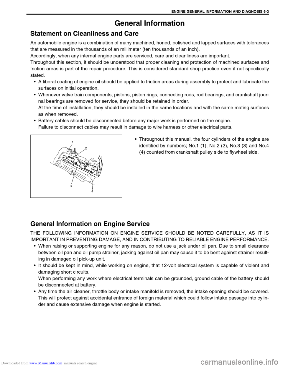
Throughout this manual, the four cylinders of the engine are
identified by numbers; No.1 (1), No.2 (2), No.3 (3) and No.4
(4) counted from crankshaft pulley side to flywheel side.
General Information on Engine Service
THE FOLLOWING INFORMATION ON ENGINE SERVICE SHOULD BE NOTED CAREFULLY, AS IT IS
IMPORTANT IN PREVENTING DAMAGE, AND IN CONTRIBUTING TO RELIABLE ENGINE PERFORMANCE.
When raising or supporting engine for any reason, do not use a jack under oil pan. Due to small clearance
between oil pan and oil pump strainer, jacking against oil pan may cause it to be bent against strainer result-
ing in damaged oil pick-up unit.
It should be kept in mind, while working on engine, that 12-volt electrical system is capable of violent and
damaging short circuits.
When performing any work where electrical terminals can be grounded, ground cable of the battery should
be disconnected at battery.
Any time the air cleaner, throttle body or intake manifold is removed, the intake opening should be covered.
This will protect against accidental entrance of foreign material which could follow intake passage into cylin-
der and cause extensive damage when engine is started.
Page 413 of 687
![SUZUKI JIMNY 2005 3.G Service Workshop Manual Downloaded from www.Manualslib.com manuals search engine 6-56 ENGINE GENERAL INFORMATION AND DIAGNOSIS
INSPECTION
[A] Fig. 1 for Step 2 / [B] Fig. 2 for Step 3 / [C] Fig. 3 for Step 4Step Action Yes N SUZUKI JIMNY 2005 3.G Service Workshop Manual Downloaded from www.Manualslib.com manuals search engine 6-56 ENGINE GENERAL INFORMATION AND DIAGNOSIS
INSPECTION
[A] Fig. 1 for Step 2 / [B] Fig. 2 for Step 3 / [C] Fig. 3 for Step 4Step Action Yes N](/manual-img/20/7588/w960_7588-412.png)
Downloaded from www.Manualslib.com manuals search engine 6-56 ENGINE GENERAL INFORMATION AND DIAGNOSIS
INSPECTION
[A] Fig. 1 for Step 2 / [B] Fig. 2 for Step 3 / [C] Fig. 3 for Step 4Step Action Yes No
1Was “Engine Diag. Flow Table” performed? Go to Step 2. Go to “Engine Diag. Flow
Table”.
2 Check TP Sensor and Its Circuit.
1) Connect scan tool to DLC with ignition
switch OFF and then turn ignition switch ON.
See Fig. 1.
2) Check throttle valve opening percentage dis-
played on scan tool.
Is it displayed 0% or 100%?Go to Step 3. Intermittent trouble.
Check for intermittent
referring to “Intermittent
and Poor Connection” in
Section 0A.
3 Check Wire Harness.
1) Disconnect connector from TP sensor with
ignition switch OFF.
2) Check for proper connection to TP sensor at
“Lg/R”, “Lg” and “B/Bl” wire terminal.
3) If OK, then with ignition switch ON, check
voltage at each of “Lg/R” and “Lg” wire ter-
minals and body ground. See Fig. 2.
Is voltage about 4 – 6 V at each terminal?Go to Step 4.“Lg/R” wire open, “Lg/R”
wire shorted to ground cir-
cuit or power circuit or
“B/Bl” wire, “Lg” wire open
or shorted to ground cir-
cuit or poor E19-22 or
E19-16 connection.
If wire and connection are
OK, substitute a known-
good ECM and recheck.
4 Check TP Sensor.
1) Check resistance between terminals of TP
sensor. See Fig. 3.
TP sensor resistance
Between 1 and 3 : 4.0 – 6.0 k
Ω
ΩΩ Ω
Between 2 and 3 : Varying according to
throttle valve opening (0.02 – 6.0 k
Ω
ΩΩ Ω)
Are measured values within specifications?“B/Bl” wire open or poor
E19-10 connection.
If wire and connection are
OK, substitute a known-
good ECM and recheck.Replace TP sensor.
Page 443 of 687

Downloaded from www.Manualslib.com manuals search engine 6-86 ENGINE GENERAL INFORMATION AND DIAGNOSIS
2) Start engine and warm it up to normal operating temperature (70 – 110 °C, 158 – 230 °F) and run it at idle
for 5 min.
3) Increase vehicle speed to 50 – 55 mph, 80 – 88 km/h in 5th gear or in “D” range.
4) Hold throttle valve at that opening position for 2 min. or longer.
5) Increase engine speed to 4000 r/min. in 3rd gear or in “2” range.
6) Release accelerator pedal and with engine brake applied, keep vehicle coasting (fuel cut condition) till
engine speed reaches 1500 r/min.
7) Stop vehicle (don’t turn ignition switch OFF) and confirm test results according to following “Test Result Con-
firmation Flow Table.”
Test Result Confirmation Flow Table
INSPECTION
Step Action Yes No
1 Check DTC in “DTC” mode and pending DTC in
“ON BOARD TEST”.
Is DTC or pending DTC displayed?Proceed to applicable
DTC flow table.Go to Step 2.
2 Set scan tool to “READINESS TESTS” mode
and check if testing has been completed.
Is test completed?No DTC is detected.
(Confirmation test is com-
pleted)Repeat DTC confirmation
procedure.
Step Action Yes No
1Was “Engine Diag. Flow Table” performed? Go to Step 2. Go to “Engine Diag. Flow
Table”.
2 1) Turn ignition switch ON.
2) Does EGR stepper motor operation for 0.6
second after ignition switch OFF?Go to Step 3. Go to Step 6.
3 With ignition switch at OFF, check voltage
between E19-28, 17, 29, 18 terminals of ECM
and body ground. See Fig. 2.
Is voltage about 0 V?Go to Step 4. Go to Step 8.
Page 482 of 687

Downloaded from www.Manualslib.com manuals search engine ENGINE MECHANICAL (M13 ENGINE) 6A1-1
6F1
6G
6H
6K
7A
7A1
7B1
7C1
7D
7E
7F
8A
8C
6A1
8E
9
9
10B
SECTION 6A1
ENGINE MECHANICAL (M13 ENGINE)
CONTENTS
General Description ......................................6A1-2
Engine ......................................................... 6A1-2
Engine Lubrication ...................................... 6A1-3
Diagnosis .......................................................6A1-4
Diagnosis Table .......................................... 6A1-4
Compression Check .................................... 6A1-4
Engine Vacuum Check ................................ 6A1-6
Oil Pressure Check ..................................... 6A1-7
Valve Lash (Clearance) ............................... 6A1-9
On-Vehicle Service......................................6A1-13
Air Cleaner Element .................................. 6A1-13
Air Cleaner Assembly ................................ 6A1-14
Knock Sensor ............................................ 6A1-14
Cylinder Head Cover ................................. 6A1-15
Throttle Body and Intake Manifold ............ 6A1-18
Exhaust Manifold ....................................... 6A1-21Oil Pan and Oil Pump Strainer .................. 6A1-24
Timing Chain Cover .................................. 6A1-28
Oil Pump ................................................... 6A1-33
Timing Chain and Chain Tensioner .......... 6A1-37
Camshaft, Tappet and Shim ..................... 6A1-42
Valves and Cylinder Head ........................ 6A1-48
Pistons, Piston Rings, Connecting
Rods and Cylinders................................... 6A1-62
Engine Mountings ..................................... 6A1-72
Unit Repair Overhaul .................................. 6A1-73
Engine Assembly ...................................... 6A1-73
Main Bearings, Crankshaft and Cylinder
Block ......................................................... 6A1-79
Required Service Material .......................... 6A1-93
Tightening Torque Specification ............... 6A1-93
Special Tool ................................................. 6A1-94
WARNING:
For vehicles equipped with Supplemental Restraint (Air Bag) System:
Service on and around the air bag system components or wiring must be performed only by an
authorized SUZUKI dealer. Refer to “Air Bag System Components and Wiring Location View” under
“General Description” in air bag system section in order to confirm whether you are performing ser-
vice on or near the air bag system components or wiring. Please observe all WARNINGS and “Ser-
vice Precautions” under “On-Vehicle Service” in air bag system section before performing service
on or around the air bag system components or wiring. Failure to follow WARNINGS could result in
unintentional activation of the system or could render the system inoperative. Either of these two
conditions may result in severe injury.
Technical service work must be started at least 90 seconds after the ignition switch is turned to the
“LOCK” position and the negative cable is disconnected from the battery. Otherwise, the system
may be activated by reserve energy in the Sensing and Diagnostic Module (SDM).
Page 495 of 687

Downloaded from www.Manualslib.com manuals search engine 6A1-14 ENGINE MECHANICAL (M13 ENGINE)
Air Cleaner Assembly
REMOVAL
1) Disconnect negative cable at battery.
2) Disconnect IAT sensor coupler (1).
3) Disconnect breather hose from air cleaner outlet No.2 hose
(2).
4) Remove air cleaner outlet No.2 hose fastening bolt (3).
5) Loosen air cleaner outlet No.2 hose clamp bolt (4).
6) Remove air cleaner case fastening bolts (5).
7) Remove air cleaner assembly with outlet hoses.
INSTALLATION
Reverse removal procedure for installation.
Knock Sensor
REMOVAL
1) Disconnect negative cable at battery.
2) Remove intake manifold referring to “Throttle Body and
Intake Manifold” in this section.
3) Disconnect knock sensor connector (1).
4) Remove knock sensor (2) from cylinder block.
INSPECTION
Check sensor for damage.
If any faulty is found, replace.
INSTALLATION
Reverse removal procedure for installation.
Tightening torque
Knock sensor (a) : 23 N·m (2.3 kg-m, 16.5 lb-ft)
Page 499 of 687

Downloaded from www.Manualslib.com manuals search engine 6A1-18 ENGINE MECHANICAL (M13 ENGINE)
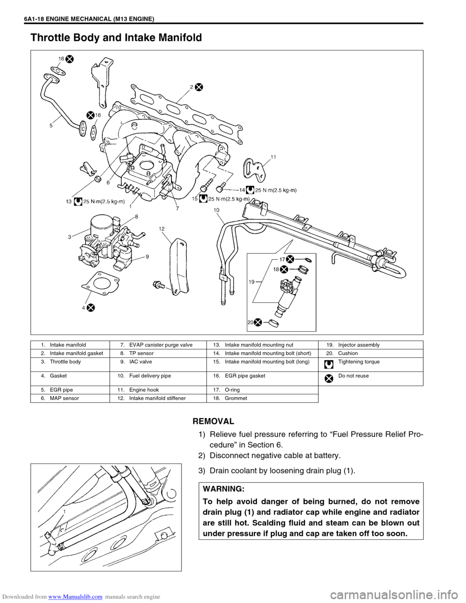
Throttle Body and Intake Manifold
REMOVAL
1) Relieve fuel pressure referring to “Fuel Pressure Relief Pro-
cedure” in Section 6.
2) Disconnect negative cable at battery.
3) Drain coolant by loosening drain plug (1).
1. Intake manifold 7. EVAP canister purge valve 13. Intake manifold mounting nut 19. Injector assembly
2. Intake manifold gasket 8. TP sensor 14. Intake manifold mounting bolt (short) 20. Cushion
3. Throttle body 9. IAC valve 15. Intake manifold mounting bolt (long) Tightening torque
4. Gasket 10. Fuel delivery pipe 16. EGR pipe gasket Do not reuse
5. EGR pipe 11. Engine hook 17. O-ring
6. MAP sensor 12. Intake manifold stiffener 18. Grommet
WARNING:
To help avoid danger of being burned, do not remove
drain plug (1) and radiator cap while engine and radiator
are still hot. Scalding fluid and steam can be blown out
under pressure if plug and cap are taken off too soon.
Page 500 of 687

Downloaded from www.Manualslib.com manuals search engine ENGINE MECHANICAL (M13 ENGINE) 6A1-19
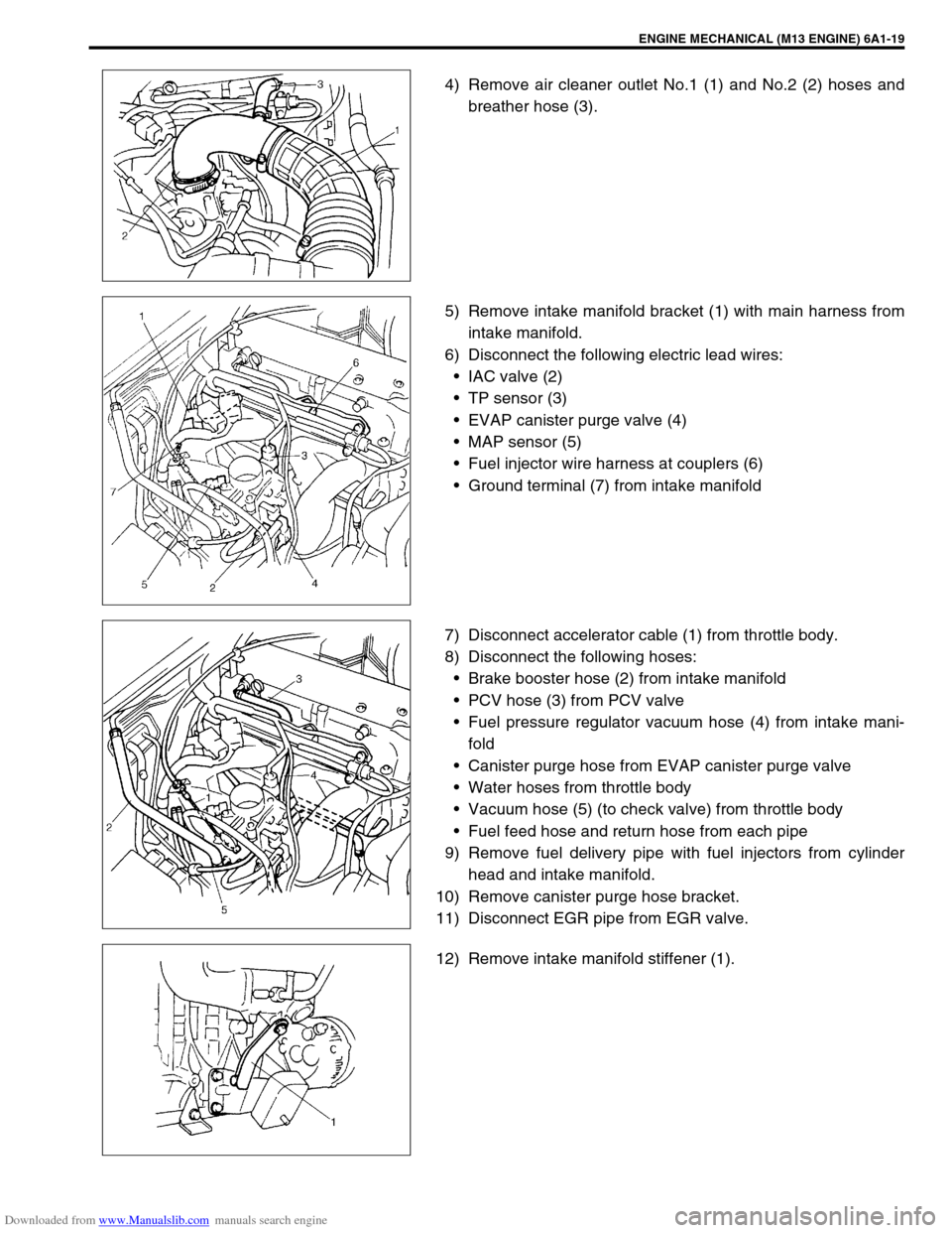
4) Remove air cleaner outlet No.1 (1) and No.2 (2) hoses and
breather hose (3).
5) Remove intake manifold bracket (1) with main harness from
intake manifold.
6) Disconnect the following electric lead wires:
IAC valve (2)
TP sensor (3)
EVAP canister purge valve (4)
MAP sensor (5)
Fuel injector wire harness at couplers (6)
Ground terminal (7) from intake manifold
7) Disconnect accelerator cable (1) from throttle body.
8) Disconnect the following hoses:
Brake booster hose (2) from intake manifold
PCV hose (3) from PCV valve
Fuel pressure regulator vacuum hose (4) from intake mani-
fold
Canister purge hose from EVAP canister purge valve
Water hoses from throttle body
Vacuum hose (5) (to check valve) from throttle body
Fuel feed hose and return hose from each pipe
9) Remove fuel delivery pipe with fuel injectors from cylinder
head and intake manifold.
10) Remove canister purge hose bracket.
11) Disconnect EGR pipe from EGR valve.
12) Remove intake manifold stiffener (1).