2005 SUZUKI JIMNY hole screw
[x] Cancel search: hole screwPage 87 of 687

Downloaded from www.Manualslib.com manuals search engine 1B-26 AIR CONDITIONING (OPTIONAL)
2) Connect Low charging hose (1) and High charging hose (2)
of the manifold gauge set (3) in position. Thus open refriger-
ant container valve (4) to purge the charging line.
3) Open the high pressure side valve (5) and charge refrigerant
to system.
4) After a while, open the low pressure side valve (6) and close
the high pressure side valve (5).
5) Start engine and keep engine speed at 1500 r/min. Then,
operate air conditioning.
6) Charge A/C system with refrigerant in vapor state. At this
time, refrigerant container should be held upright.
7) When refrigerant container (3) is emptied, use the following
procedure to replace refrigerant container with a new refrig-
erant container (3).
a) Close low pressure valve.
b) Replace empty container (3) with a refrigerant container
which has been charged with refrigerant. When using
refrigerant container tap valve (4), use the following proce-
dure for replacement.
i) Retract needle (1) and remove refrigerant container tap
valve (4) by loosening its plate nut (2).
ii) Install previously-removed refrigerant container tap valve
(4) to a new refrigerant container (3).
c) Purge any air existing in center charging hose
When using refrigerant container tap valve, use the follow-
ing procedure to purge air.
i) Once fully tighten refrigerant container tap valve (1), and
then loosen (open) plate nut (2) slightly.
ii) Open low pressure side valve (3) of manifold gauge set
(4) a little.
iii) As soon as refrigerant comes out with a “hiss” through a
clearance between refrigerant container and tap valve,
tighten plate nut (2) as well as low pressure side valve (3).
iv) Turn handle of tap valve (1) clockwise so that its needle is
screwed into the new container to make a hole for refriger-
ant flow. WARNING:
Make sure that high pressure side valve is closed
securely.
Page 104 of 687

Downloaded from www.Manualslib.com manuals search engine AIR CONDITIONING (OPTIONAL) 1B-43
4) Remove circlip (1) using special tool.
Special tool
(A) : 09900-06107
5) Remove magnet clutch lead wire clamp screw, and discon-
nect magnet clutch lead wire.
6) Remove magnet clutch pulley (1) by using a puller (2).
7) Remove snap ring (1) using special tool.
Special tool
(A) : 09900-06107
8) Remove magnet clutch coil (2) from compressor body
assembly (3).
INSTALLATION
1) Install magnet clutch coil (1).
2) Install snap ring (3) to proper direction as show using special
tool.
Special tool
(A) : 09900-06107
NOTE:
Be careful not to damage pulley part.
NOTE:
Protrusion on under side of magnet clutch coil (1) must
match hole in compressor body assembly (2).
Page 155 of 687

Downloaded from www.Manualslib.com manuals search engine 3C-2 STEERING WHEEL AND COLUMN
General Description
This double tube type steering column has the following three important features in addition to the steering func-
tion:
The column is energy absorbing, designed to compress in a front-end collision.
The ignition switch and lock are mounted conveniently on this column.
With the column mounted lock, the ignition and steering operations can be locked to inhibit theft of the vehi-
cle.
To insure the energy absorbing action, it is important that only the specified screws, bolts and nuts be used as
designated and that they are tightened to the specified torque.
When the column assembly is removed from the vehicle, special care must be taken in handling it. Use of a
steering wheel puller other than the one recommended in this manual or a sharp blow on the end of the steering
shaft, leaning on the assembly, or dropping the assembly could shear the plastic shear pins which maintain col-
umn length and position.
The driver air bag (inflator) module is one of the supplemental restraint (air bag) system components and is
mounted to the center of the steering wheel. During certain frontal crashes, the air bag system supplements the
restraint of the driver’s and passenger’s seat belts by deploying the air bags.
The air bag (inflator) module should be handled with care to prevent accidental deployment. When servicing, be
sure to observe all WARNINGS and CAUTIONS in this section and “Service Precautions” in Section 10B.
1. Driver air bag (inflator) module 6. Steering column upper cover 11. Steering lower shaft
2. Steering wheel 7. Steering column lower cover [A] : For vehicle with air bag system
3. Steering wheel side cap 8. Steering column assembly [B] : For vehicle without air bag system
4. Steering wheel nut 9. Steering lock assembly (ignition switch)
5. Combination switch or contact coil and com-
bination switch assembly10. Steering column hole cover
Page 159 of 687

Downloaded from www.Manualslib.com manuals search engine 3C-6 STEERING WHEEL AND COLUMN
REMOVAL
1) Disconnect negative battery cable at battery terminal.
2) Remove steering wheel pad (for vehicle without air bag sys-
tem) or driver air bag (inflator) module (for vehicle with air
bag system) as follows.
Vehicle without air bag system for TYPE A
a) Remove steering wheel pad.
b) Disconnect horn connector.
Vehicle without air bag system for TYPE B
a) As shown in the figure, while pushing the set spring (1) with
a screwdriver or the like inserted in the hole of the steering
wheel, pull the lower part of the pad forward and remove
the steering wheel pad.
Vehicle with air bag system
a) Remove driver air bag (inflator) module from steering wheel
referring to “Driver Air Bag (Inflator) Module” in this section.
3) Remove steering shaft nut.
4) Make alignment marks (1) on steering wheel and shaft for a
guide during reinstallation.
[A] : For TYPE A
[B] : For TYPE B
Page 162 of 687

Downloaded from www.Manualslib.com manuals search engine STEERING WHEEL AND COLUMN 3C-9
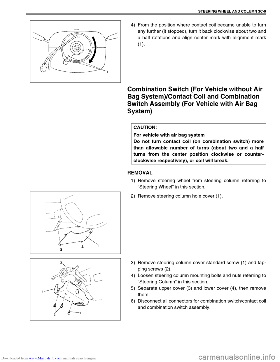
4) From the position where contact coil became unable to turn
any further (it stopped), turn it back clockwise about two and
a half rotations and align center mark with alignment mark
(1).
Combination Switch (For Vehicle without Air
Bag System)/Contact Coil and Combination
Switch Assembly (For Vehicle with Air Bag
System)
REMOVAL
1) Remove steering wheel from steering column referring to
“Steering Wheel” in this section.
2) Remove steering column hole cover (1).
3) Remove steering column cover standard screw (1) and tap-
ping screws (2).
4) Loosen steering column mounting bolts and nuts referring to
“Steering Column” in this section.
5) Separate upper cover (3) and lower cover (4), then remove
them.
6) Disconnect all connectors for combination switch/contact coil
and combination switch assembly.
CAUTION:
For vehicle with air bag system
Do not turn contact coil (on combination switch) more
than allowable number of turns (about two and a half
turns from the center position clockwise or counter-
clockwise respectively), or coil will break.
Page 199 of 687

Downloaded from www.Manualslib.com manuals search engine 3D-26 FRONT SUSPENSION
For 2WD model:
a) Using lock plate (1), lock bearing lock nut. If lock screw hole
is not aligned with screw hole in lock nut, turn lock nut in
tightening direction till they align.
Tightening torque
Wheel bearing lock washer screw
(a) : 1.5 N·m (0.15 kg-m, 1.0 lb-ft)
b) Remove grease, old sealant and dusts from mating sur-
faces of hub cap (1) and wheel hub (2) to clean, apply
water tight sealant to hub cap mating surface evenly, and
install hub cap (1) to wheel hub (2).
“A” : Sealant 99000-31090
For 4WD model:
a) Caulk front wheel bearing lock nut at groove of spindle.
b) Apply lithium grease thinly to both surface, all around of
front spindle thrust washer (1).
“A” : Grease 99000-25010
NOTE:
When installing hub cap (1), hammer lightly several
locations on the collar of cap until collar comes closely
into contact with wheel hub (2).
If fitting part of cap is deformed or damaged or if it is
fitted loosely, replace with new one.
Page 200 of 687

Downloaded from www.Manualslib.com manuals search engine FRONT SUSPENSION 3D-27
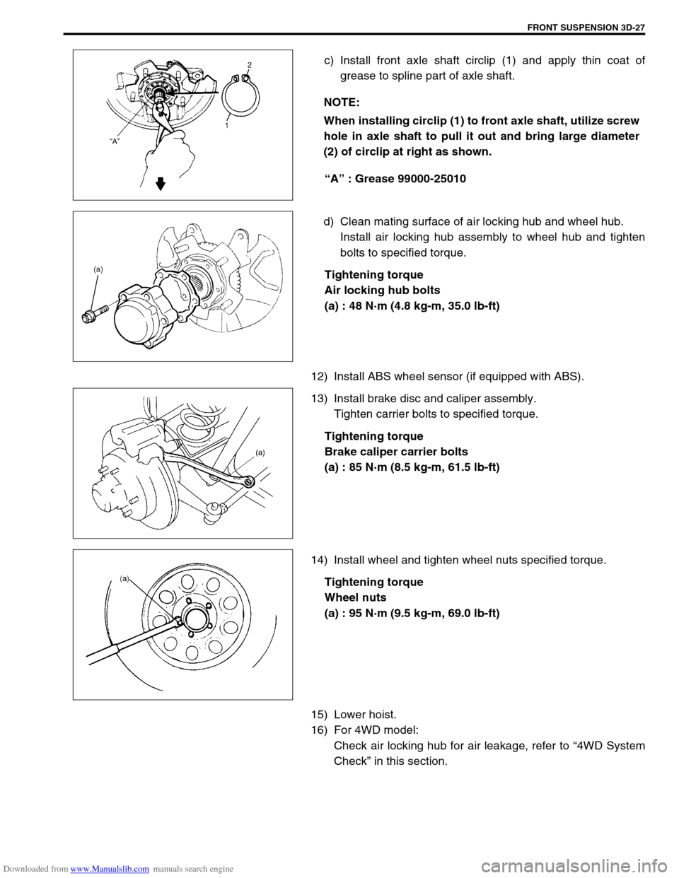
c) Install front axle shaft circlip (1) and apply thin coat of
grease to spline part of axle shaft.
“A” : Grease 99000-25010
d) Clean mating surface of air locking hub and wheel hub.
Install air locking hub assembly to wheel hub and tighten
bolts to specified torque.
Tightening torque
Air locking hub bolts
(a) : 48 N·m (4.8 kg-m, 35.0 lb-ft)
12) Install ABS wheel sensor (if equipped with ABS).
13) Install brake disc and caliper assembly.
Tighten carrier bolts to specified torque.
Tightening torque
Brake caliper carrier bolts
(a) : 85 N·m (8.5 kg-m, 61.5 lb-ft)
14) Install wheel and tighten wheel nuts specified torque.
Tightening torque
Wheel nuts
(a) : 95 N·m (9.5 kg-m, 69.0 lb-ft)
15) Lower hoist.
16) For 4WD model:
Check air locking hub for air leakage, refer to “4WD System
Check” in this section. NOTE:
When installing circlip (1) to front axle shaft, utilize screw
hole in axle shaft to pull it out and bring large diameter
(2) of circlip at right as shown.
Page 635 of 687

Downloaded from www.Manualslib.com manuals search engine 6E-30 ENGINE AND EMISSION CONTROL SYSTEM
Throttle position sensor (TP sensor)
INSPECTION
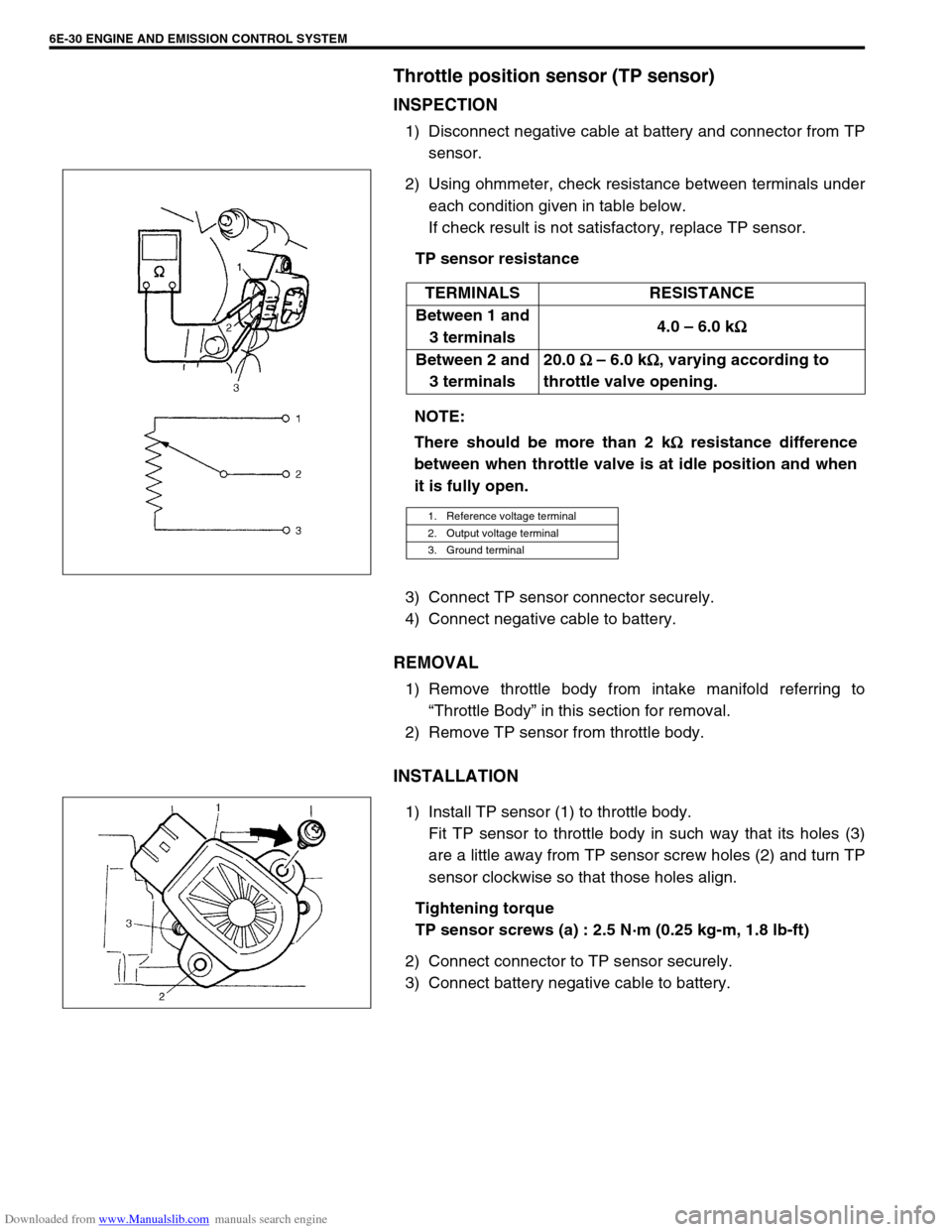
1) Disconnect negative cable at battery and connector from TP
sensor.
2) Using ohmmeter, check resistance between terminals under
each condition given in table below.
If check result is not satisfactory, replace TP sensor.
TP sensor resistance
3) Connect TP sensor connector securely.
4) Connect negative cable to battery.
REMOVAL
1) Remove throttle body from intake manifold referring to
“Throttle Body” in this section for removal.
2) Remove TP sensor from throttle body.
INSTALLATION
1) Install TP sensor (1) to throttle body.
Fit TP sensor to throttle body in such way that its holes (3)
are a little away from TP sensor screw holes (2) and turn TP
sensor clockwise so that those holes align.
Tightening torque
TP sensor screws (a) : 2.5 N·m (0.25 kg-m, 1.8 lb-ft)
2) Connect connector to TP sensor securely.
3) Connect battery negative cable to battery.TERMINALS RESISTANCE
Between 1 and
3 terminals4.0 – 6.0 k
Ω
ΩΩ Ω
Between 2 and
3 terminals20.0
Ω
ΩΩ Ω – 6.0 k
Ω
ΩΩ Ω, varying according to
throttle valve opening.
NOTE:
There should be more than 2 k
Ω
ΩΩ Ω resistance difference
between when throttle valve is at idle position and when
it is fully open.
1. Reference voltage terminal
2. Output voltage terminal
3. Ground terminal