2005 SUZUKI JIMNY Head torque
[x] Cancel search: Head torquePage 27 of 687

Downloaded from www.Manualslib.com manuals search engine 0A-22 GENERAL INFORMATION
LLH
LSPVLeft Hand
Load Sensing Proportioning Valve
TTBI
TCC
TCM
TP Sensor
TVV
TWC
2WDThrottle Body Fuel Injection
(Single-Point Fuel Injection, SPI)
Torque Converter Clutch
Transmission Control Module
(A/T Controller, A/T Control Mod-
ule)
Throttle Position Sensor
Thermal Vacuum Valve
(Thermal Vacuum Switching Valve,
TVSV, Bimetal Vacuum Switching
Valve, BVSV)
Three Way Catalytic Converter
(Three Way Catalyst)
2 Wheel Drive MMAF Sensor
MAP Sensor
Max
MFI
Min
MIL
M/TMass Air Flow Sensor
(Air Flow Sensor, AFS, Air Flow
Meter, AFM)
Manifold Absolute Pressure
Sensor (Pressure Sensor, PS)
Maximum
Multiport Fuel Injection
(Multipoint Fuel Injection)
Minimum
Malfunction Indicator Lamp
(“CHECK ENGINE” Light)
Manual Transmission
N NOx Nitrogen Oxides VVIN
VSSVehicle Identification Number
Vehicle Speed Sensor
OOBD
O/D
OHCOn-Board Diagnostic System
(Self-Diagnosis Function)
Overdrive
Over Head CamshaftWWU-OC
WU-TWCWarm Up Oxidation Catalytic
Converter
Warm Up Three Way Catalytic
Converter
PPNP
P/S
PSP Switch
PCM
PCVPark/Neutral Position
Power Steering
Power Steering Pressure Switch
(P/S Pressure Switch)
Powertrain Control Module
Positive Crankcase Ventilation
R RH Right Hand
SSAE
SDM
SFI
SOHCSociety of Automotive Engineers
Sensing and Diagnostic Module
(Air bag controller, Air bag control
module)
Sequential Multiport Fuel Injection
Single Over Head Camshaft
Page 29 of 687

Downloaded from www.Manualslib.com manuals search engine 0A-24 GENERAL INFORMATION
Fasteners Information
Metric Fasteners
Most of the fasteners used for this vehicle are metric fasteners. When replacing any fasteners, it is most impor-
tant that replacement fasteners be the correct diameter, thread pitch and strength.
Fastener Strength Identification
Most commonly used metric fastener strength property classes are 4T, 6.8, 7T, 8.8 and radial line with the class
identification embossed on the head of each bolt. Some metric nuts will be marked with punch, 6 or 8 mark
strength identification on the nut face. Figure shows the different strength markings.
When replacing metric fasteners, be careful to use bolts and nuts of the same strength or greater than the origi-
nal fasteners (the same number marking or higher). It is likewise important to select replacement fasteners of
the correct diameter and thread pitch. Correct replacement bolts and nuts are available through the parts divi-
sion.
Metric bolts: Identification class numbers or marks correspond to bolt strength (increasing numbers represent
increasing strength).
Standard Tightening Torque
Each fastener should be tightened to the torque specified in each section of this manual. If no description or
specification is provided, refer to the following tightening torque chart for the applicable torque for each fastener.
When a fastener of greater strength than the original one is used, however, use the torque specified for the orig-
inal fastener.
1. Nuts strength identification
NOTE:
For the flanged bolt, flanged nut and self-lock nut of 4T and 7T strength, add 10% to the tightening
torque given in the chart below.
The chart below is applicable only where the fastened parts are made of steel light alloy.
Page 102 of 687

Downloaded from www.Manualslib.com manuals search engine AIR CONDITIONING (OPTIONAL) 1B-41
Magnet Clutch
1. Thermal switch 6. Magnet clutch coil a. Front head bolt
: Tighten bolt “a” first, and next “b”.
2. Compressor body assembly 7. Compressor pulley b. Front head bolt
: Tighten bolt “a” first, and next “b”.
3. O-ring 8. Circlip c. Clutch plate bolt
4. Lip seal 9. Shim Tightening torque
5. Front head 10. Clutch plate Do not reuse.
Page 107 of 687

Downloaded from www.Manualslib.com manuals search engine 1B-46 AIR CONDITIONING (OPTIONAL)
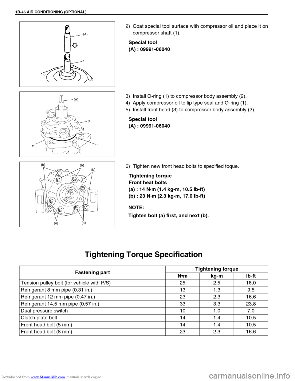
2) Coat special tool surface with compressor oil and place it on
compressor shaft (1).
Special tool
(A) : 09991-06040
3) Install O-ring (1) to compressor body assembly (2).
4) Apply compressor oil to lip type seal and O-ring (1).
5) Install front head (3) to compressor body assembly (2).
Special tool
(A) : 09991-06040
6) Tighten new front head bolts to specified toque.
Tightening torque
Front heat bolts
(a) : 14 N·m (1.4 kg-m, 10.5 lb-ft)
(b) : 23 N·m (2.3 kg-m, 17.0 lb-ft)
Tightening Torque Specification
NOTE:
Tighten bolt (a) first, and next (b).
Fastening partTightening torque
Nm kg-m lb-ft
Tension pulley bolt (for vehicle with P/S) 25 2.5 18.0
Refrigerant 8 mm pipe (0.31 in.) 13 1.3 9.5
Refrigerant 12 mm pipe (0.47 in.) 23 2.3 16.6
Refrigerant 14.5 mm pipe (0.57 in.) 33 3.3 23.8
Dual pressure switch 10 1.0 7.0
Clutch plate bolt 14 1.4 10.5
Front head bolt (5 mm) 14 1.4 10.5
Front head bolt (8 mm) 23 2.3 16.6
Page 161 of 687

Downloaded from www.Manualslib.com manuals search engine 3C-8 STEERING WHEEL AND COLUMN
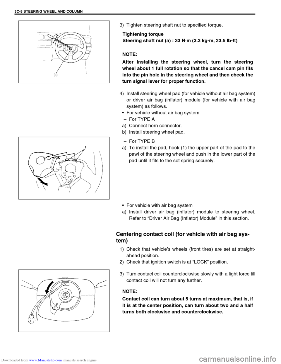
3) Tighten steering shaft nut to specified torque.
Tightening torque
Steering shaft nut (a) : 33 N·m (3.3 kg-m, 23.5 lb-ft)
4) Install steering wheel pad (for vehicle without air bag system)
or driver air bag (inflator) module (for vehicle with air bag
system) as follows.
For vehicle without air bag system
–For TYPE A
a) Connect horn connector.
b) Install steering wheel pad.
–For TYPE B
a) To install the pad, hook (1) the upper part of the pad to the
pawl of the steering wheel and push in the lower part of the
pad until it fits to the set spring securely.
For vehicle with air bag system
a) Install driver air bag (inflator) module to steering wheel.
Refer to “Driver Air Bag (Inflator) Module” in this section.
Centering contact coil (for vehicle with air bag sys-
tem)
1) Check that vehicle’s wheels (front tires) are set at straight-
ahead position.
2) Check that ignition switch is at “LOCK” position.
3) Turn contact coil counterclockwise slowly with a light force till
contact coil will not turn any further. NOTE:
After installing the steering wheel, turn the steering
wheel about 1 full rotation so that the cancel cam pin fits
into the pin hole in the steering wheel and then check the
turn signal lever for proper function.
NOTE:
Contact coil can turn about 5 turns at maximum, that is, if
it is at the center position, can turn about two and a half
turns both clockwise and counterclockwise.
Page 482 of 687

Downloaded from www.Manualslib.com manuals search engine ENGINE MECHANICAL (M13 ENGINE) 6A1-1
6F1
6G
6H
6K
7A
7A1
7B1
7C1
7D
7E
7F
8A
8C
6A1
8E
9
9
10B
SECTION 6A1
ENGINE MECHANICAL (M13 ENGINE)
CONTENTS
General Description ......................................6A1-2
Engine ......................................................... 6A1-2
Engine Lubrication ...................................... 6A1-3
Diagnosis .......................................................6A1-4
Diagnosis Table .......................................... 6A1-4
Compression Check .................................... 6A1-4
Engine Vacuum Check ................................ 6A1-6
Oil Pressure Check ..................................... 6A1-7
Valve Lash (Clearance) ............................... 6A1-9
On-Vehicle Service......................................6A1-13
Air Cleaner Element .................................. 6A1-13
Air Cleaner Assembly ................................ 6A1-14
Knock Sensor ............................................ 6A1-14
Cylinder Head Cover ................................. 6A1-15
Throttle Body and Intake Manifold ............ 6A1-18
Exhaust Manifold ....................................... 6A1-21Oil Pan and Oil Pump Strainer .................. 6A1-24
Timing Chain Cover .................................. 6A1-28
Oil Pump ................................................... 6A1-33
Timing Chain and Chain Tensioner .......... 6A1-37
Camshaft, Tappet and Shim ..................... 6A1-42
Valves and Cylinder Head ........................ 6A1-48
Pistons, Piston Rings, Connecting
Rods and Cylinders................................... 6A1-62
Engine Mountings ..................................... 6A1-72
Unit Repair Overhaul .................................. 6A1-73
Engine Assembly ...................................... 6A1-73
Main Bearings, Crankshaft and Cylinder
Block ......................................................... 6A1-79
Required Service Material .......................... 6A1-93
Tightening Torque Specification ............... 6A1-93
Special Tool ................................................. 6A1-94
WARNING:
For vehicles equipped with Supplemental Restraint (Air Bag) System:
Service on and around the air bag system components or wiring must be performed only by an
authorized SUZUKI dealer. Refer to “Air Bag System Components and Wiring Location View” under
“General Description” in air bag system section in order to confirm whether you are performing ser-
vice on or near the air bag system components or wiring. Please observe all WARNINGS and “Ser-
vice Precautions” under “On-Vehicle Service” in air bag system section before performing service
on or around the air bag system components or wiring. Failure to follow WARNINGS could result in
unintentional activation of the system or could render the system inoperative. Either of these two
conditions may result in severe injury.
Technical service work must be started at least 90 seconds after the ignition switch is turned to the
“LOCK” position and the negative cable is disconnected from the battery. Otherwise, the system
may be activated by reserve energy in the Sensing and Diagnostic Module (SDM).
Page 493 of 687

Downloaded from www.Manualslib.com manuals search engine 6A1-12 ENGINE MECHANICAL (M13 ENGINE)
8) Lift valve by turning crankshaft counterclockwise (in opposite
direction against above Step 4) and remove special tool.
Special tool
(A) : 09916-67020
9) Install camshaft housing (1) and tighten them to specified
torque.
Tightening torque
Camshaft housing bolts (a) : 11 N·m (1.1 kg-m, 8.0 lb-ft)
10) Check valve clearance again.
11) Install cylinder head cover, referring to “Cylinder Head
Cover” in this section.
1. Tappet
2. Camshaft
Page 498 of 687

Downloaded from www.Manualslib.com manuals search engine ENGINE MECHANICAL (M13 ENGINE) 6A1-17
3) Install cylinder head cover to cylinder head.
4) Tighten bolts in such order as indicated in figure a little at a
time till they are tightened to specified torque.
Tightening torque
Cylinder head cover bolts (a) : 8 N·m (0.8 kg-m, 6.0 lb-ft)
5) Connect breather hose (1) and PCV hose (2).
6) Install oil level gauge (3).
7) Install ignition coil assemblies with high-tension cord.
8) Connect ignition coil couplers.
9) Install cylinder head upper cover.
10) Connect accelerator cable to clamp (For left hand steering
vehicle only).
11) Connect negative cable at battery.NOTE:
When installing cylinder head cover, use care so that cyl-
inder head cover gasket or spark plug hole gaskets will
not get out of place or fall off.