Page 523 of 687
Downloaded from www.Manualslib.com manuals search engine 6A1-42 ENGINE MECHANICAL (M13 ENGINE)
Camshaft, Tappet and Shim
REMOVAL
1) Remove cylinder head cover and oil pan referring to “Cylin-
der Head Cover” and “Oil Pan and Oil Pump Strainer” in this
section.
2) Remove timing chain cover referring to “Timing Chain Cover”
in this section.
3) Remove timing chain referring to “Timing Chain and Chain
Tensioner” in this section.
4) Loosen camshaft housing bolts in such order as indicated in
figure and remove them.
5) Remove camshaft housings.
6) Remove intake and exhaust camshafts.
1. Intake camshaft 4. Tappet Tightening torque
2. Exhaust camshaft 5. Camshaft housing Apply engine oil to sliding surface of each part.
3. Shim
: Shim No. on it faces tappet side.6. Camshaft housing bolt
Page 525 of 687

Downloaded from www.Manualslib.com manuals search engine 6A1-44 ENGINE MECHANICAL (M13 ENGINE)
Check clearance by using gauging plastic. Checking procedure is
as follows.
1) Clean housings and camshaft journals.
2) Remove all tappets with shims.
3) Install camshafts to cylinder head.
4) Place a piece of gauging plastic to full width of journal of
camshaft (parallel to camshaft).
5) Install camshaft housing.
6) Tighten camshaft housing bolts in such order as indicated in
figure a little at a time till they are tightened to specified
torque.
Tightening torque
Camshaft housing bolts (a) : 11 N·m (1.1 kg-m, 8.0 lb-ft)
7) Remove housing, and using scale (2) on gauging plastic (1)
envelop, measure gauging plastic width at its widest point.
Camshaft journal clearance
If measured camshaft journal clearance exceeds limit, measure
journal (housing) bore and outside diameter of camshaft journal.
Replace camshaft or cylinder head assembly whichever the dif-
ference from specification is greater.
Camshaft journal outside diameter [A]
Camshaft journal bore diameter [B] NOTE:
Do not rotate camshaft while gauging plastic is installed.
Standard Limit
0.045 – 0.087 mm
(0.0018 – 0.0034 in.)0.12 mm
(0.0047 in.)
Item Standard
No.126.934 – 26.955 mm
(1.0604 – 1.0612 in.)
Other22.934 – 22.955 mm
(0.9029 – 0.9037 in.)
Item Standard
No.127.000 – 27.021 mm
(1.0630 – 1.0638 in.)
Other23.000 – 23.021 mm
(0.9055 – 0.9063 in.)
Page 528 of 687

Downloaded from www.Manualslib.com manuals search engine ENGINE MECHANICAL (M13 ENGINE) 6A1-47
5) After applying engine oil to housing bolts, tighten them tem-
porarily first. Then tighten them by the following numerical
order in figure. Tighten a little at a time and evenly among
bolts and repeat tightening sequence two or three times
before they are tightened to specified torque.
Tightening torque
Camshaft housing bolts (a) : 11 N·m (1.1 kg-m, 8.0 lb-ft)
6) Install timing chain with crankshaft sprocket referring to
“Timing Chain and Chain Tensioner” in this section.
7) Install timing chain cover referring to “Timing Chain Cover” in
this section.
8) Check valve lashes referring to “Valve Lash” in this section.
9) Install cylinder head cover and oil pan referring to “Cylinder
Head Cover” and “Oil Pan and Oil Pump Strainer” in this sec-
tion.
10) Install radiator with cooling fan and connect A/T fluid hoses
(vehicle with A/T), radiator inlet and outlet hoses referring to
“Water Pump Belt and Cooling Fan” and “Radiator” in Sec-
tion 6B.
11) Adjust generator belt tension referring to “Water Pump Belt
Tension” in Section 6B.
12) Adjust A/C compressor and/or P/S pump belt tension (if
equipped) referring to “Compressor Drive Belt” in Section 1B
or “Power Steering Belt” in Section 3B1.
13) Refill cooling system with coolant, engine with engine oil and
A/T with specified A/T fluid (vehicle with A/T).
14) Verify that there is no coolant leakage, oil leakage and A/T
fluid leakage (vehicle with A/T) at each connection.
Page 529 of 687
Downloaded from www.Manualslib.com manuals search engine 6A1-48 ENGINE MECHANICAL (M13 ENGINE)
Valves and Cylinder Head
1. Valve cotters 6. Intake valve 11. Cylinder head gasket
: “TOP” mark provided on gasket comes to
crankshaft pulley side, facing up.
2. Valve spring retainer 7. Exhaust valve 12. Knock pin
3. Valve spring 8. Valve guide Tightening torque
4. Valve stem seal 9. Cylinder head bolt
1) Tighten all bolts at 40 N·m (4.0 kg-m)
2) Turn all bolts to 60°
3) Then, turn all bolts to 60° once againDo not reuse.
5. Valve spring seat 10. Cylinder head
Apply engine oil to sliding surface of each
part.
Page 541 of 687

Downloaded from www.Manualslib.com manuals search engine 6A1-60 ENGINE MECHANICAL (M13 ENGINE)
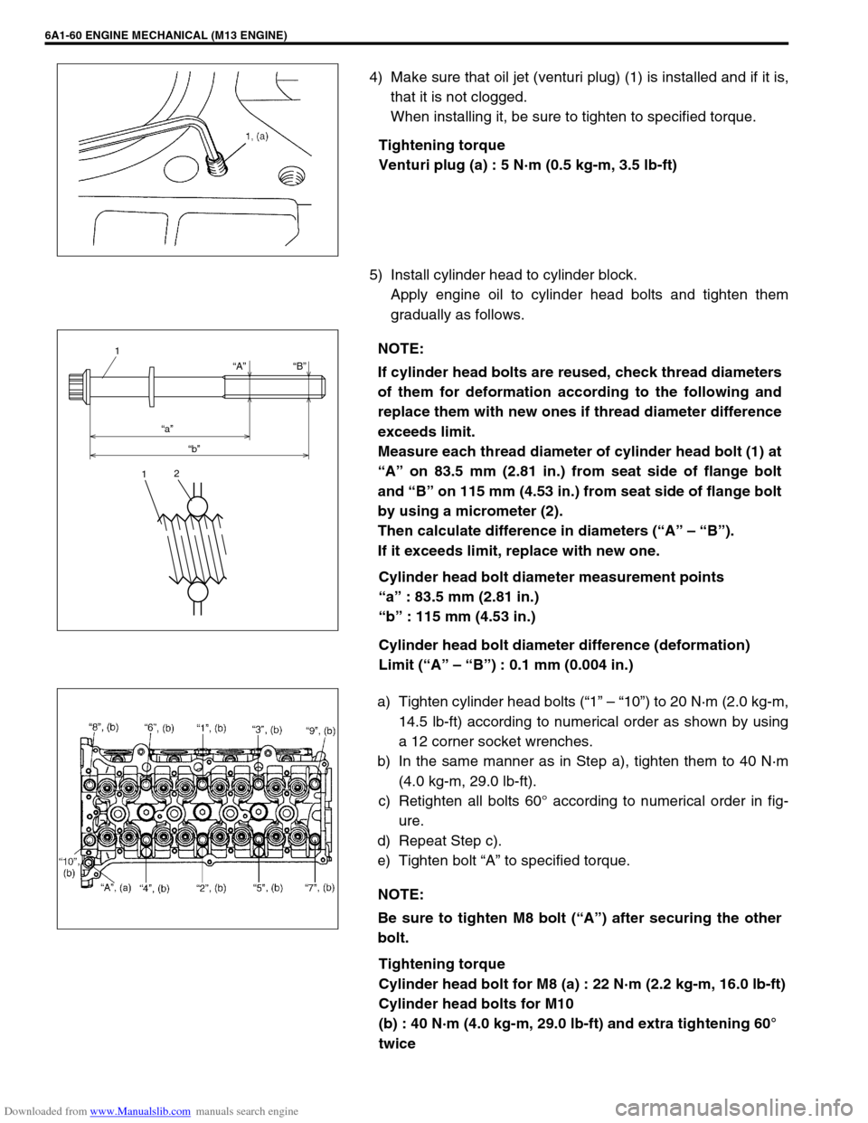
4) Make sure that oil jet (venturi plug) (1) is installed and if it is,
that it is not clogged.
When installing it, be sure to tighten to specified torque.
Tightening torque
Venturi plug (a) : 5 N·m (0.5 kg-m, 3.5 lb-ft)
5) Install cylinder head to cylinder block.
Apply engine oil to cylinder head bolts and tighten them
gradually as follows.
Cylinder head bolt diameter measurement points
“a” : 83.5 mm (2.81 in.)
“b” : 115 mm (4.53 in.)
Cylinder head bolt diameter difference (deformation)
Limit (“A” – “B”) : 0.1 mm (0.004 in.)
a) Tighten cylinder head bolts (“1” – “10”) to 20 N·m (2.0 kg-m,
14.5 lb-ft) according to numerical order as shown by using
a 12 corner socket wrenches.
b) In the same manner as in Step a), tighten them to 40 N·m
(4.0 kg-m, 29.0 lb-ft).
c) Retighten all bolts 60° according to numerical order in fig-
ure.
d) Repeat Step c).
e) Tighten bolt “A” to specified torque.
Tightening torque
Cylinder head bolt for M8 (a) : 22 N·m (2.2 kg-m, 16.0 lb-ft)
Cylinder head bolts for M10
(b) : 40 N·m (4.0 kg-m, 29.0 lb-ft) and extra tightening 60°
twice
NOTE:
If cylinder head bolts are reused, check thread diameters
of them for deformation according to the following and
replace them with new ones if thread diameter difference
exceeds limit.
Measure each thread diameter of cylinder head bolt (1) at
“A” on 83.5 mm (2.81 in.) from seat side of flange bolt
and “B” on 115 mm (4.53 in.) from seat side of flange bolt
by using a micrometer (2).
Then calculate difference in diameters (“A” – “B”).
If it exceeds limit, replace with new one.
“A”
“a”
“b”“B”
1
12
NOTE:
Be sure to tighten M8 bolt (“A”) after securing the other
bolt.
Page 543 of 687

Downloaded from www.Manualslib.com manuals search engine 6A1-62 ENGINE MECHANICAL (M13 ENGINE)
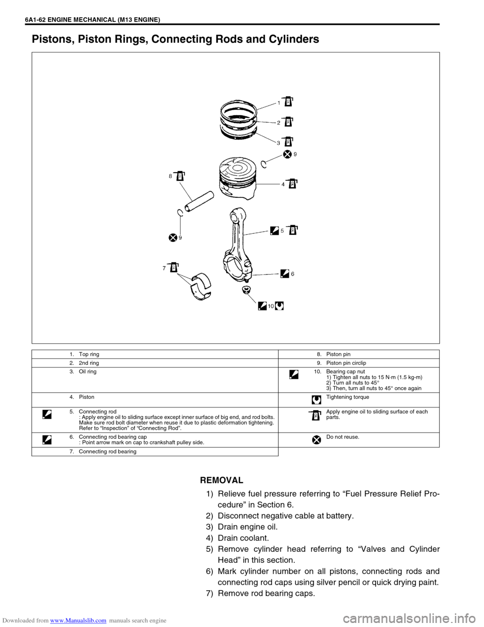
Pistons, Piston Rings, Connecting Rods and Cylinders
REMOVAL
1) Relieve fuel pressure referring to “Fuel Pressure Relief Pro-
cedure” in Section 6.
2) Disconnect negative cable at battery.
3) Drain engine oil.
4) Drain coolant.
5) Remove cylinder head referring to “Valves and Cylinder
Head” in this section.
6) Mark cylinder number on all pistons, connecting rods and
connecting rod caps using silver pencil or quick drying paint.
7) Remove rod bearing caps.
1. Top ring8. Piston pin
2. 2nd ring9. Piston pin circlip
3. Oil ring10. Bearing cap nut
1) Tighten all nuts to 15 N·m (1.5 kg-m)
2) Turn all nuts to 45°
3) Then, turn all nuts to 45° once again
4. PistonTightening torque
5. Connecting rod
: Apply engine oil to sliding surface except inner surface of big end, and rod bolts.
Make sure rod bolt diameter when reuse it due to plastic deformation tightening.
Refer to “Inspection” of “Connecting Rod”.Apply engine oil to sliding surface of each
parts.
6. Connecting rod bearing cap
: Point arrow mark on cap to crankshaft pulley side.Do not reuse.
7. Connecting rod bearing
Page 556 of 687

Downloaded from www.Manualslib.com manuals search engine ENGINE MECHANICAL (M13 ENGINE) 6A1-75
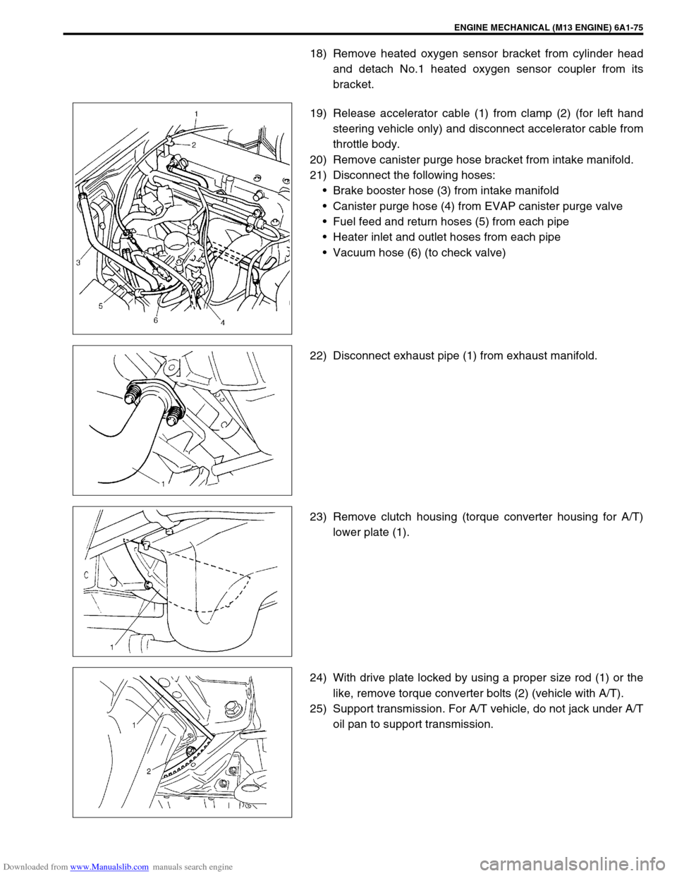
18) Remove heated oxygen sensor bracket from cylinder head
and detach No.1 heated oxygen sensor coupler from its
bracket.
19) Release accelerator cable (1) from clamp (2) (for left hand
steering vehicle only) and disconnect accelerator cable from
throttle body.
20) Remove canister purge hose bracket from intake manifold.
21) Disconnect the following hoses:
Brake booster hose (3) from intake manifold
Canister purge hose (4) from EVAP canister purge valve
Fuel feed and return hoses (5) from each pipe
Heater inlet and outlet hoses from each pipe
Vacuum hose (6) (to check valve)
22) Disconnect exhaust pipe (1) from exhaust manifold.
23) Remove clutch housing (torque converter housing for A/T)
lower plate (1).
24) With drive plate locked by using a proper size rod (1) or the
like, remove torque converter bolts (2) (vehicle with A/T).
25) Support transmission. For A/T vehicle, do not jack under A/T
oil pan to support transmission.
Page 573 of 687

Downloaded from www.Manualslib.com manuals search engine 6A1-92 ENGINE MECHANICAL (M13 ENGINE)
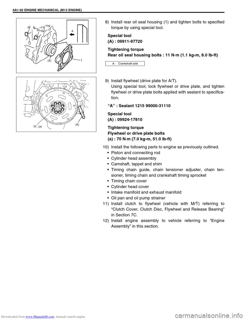
8) Install rear oil seal housing (1) and tighten bolts to specified
torque by using special tool.
Special tool
(A) : 09911-97720
Tightening torque
Rear oil seal housing bolts : 11 N·m (1.1 kg-m, 8.0 lb-ft)
9) Install flywheel (drive plate for A/T).
Using special tool, lock flywheel or drive plate, and tighten
flywheel or drive plate bolts applied with sealant to specifica-
tion.
“A” : Sealant 1215 99000-31110
Special tool
(A) : 09924-17810
Tightening torque
Flywheel or drive plate bolts
(a) : 70 N·m (7.0 kg-m, 51.0 lb-ft)
10) Install the following parts to engine as previously outlined.
Piston and connecting rod
Cylinder head assembly
Camshaft, tappet and shim
Timing chain guide, chain tensioner adjuster, chain ten-
sioner, timing chain and crankshaft timing sprocket
Timing chain cover
Cylinder head cover
Intake manifold and exhaust manifold
Oil pan and oil pump strainer
11) Install clutch to flywheel (vehicle with M/T) referring to
“Clutch Cover, Clutch Disc, Flywheel and Release Bearing”
in Section 7C.
12) Install engine assembly to vehicle referring to “Engine
Assembly” in this section.
A : Crankshaft side