2005 SUZUKI JIMNY radiator
[x] Cancel search: radiatorPage 12 of 687

Downloaded from www.Manualslib.com manuals search engine GENERAL INFORMATION 0A-7
General Precautions
The WARNING and CAUTION below describe some general precautions that you should observe when servic-
ing a vehicle. These general precautions apply to many of the service procedures described in this manual, and
they will not necessarily be repeated with each procedure to which they apply.
Before starting any service work, cover fenders, seats
and any other parts that are likely to get scratched or
stained during servicing. Also, be aware that what you
wear (e.g, buttons) may cause damage to the vehicle’s
finish.
When performing service to electrical parts that does
not require use of battery power, disconnect the nega-
tive cable of the battery. WARNING:
Whenever raising a vehicle for service, be sure to follow the instructions under “Vehicle Lifting
Points” in this section.
When it is necessary to do service work with the engine running, make sure that the parking brake
is set fully and the transmission is in Neutral (for manual transmission vehicles) or Park (for auto-
matic transmission vehicles), Keep hands, hair, clothing, tools, etc. away from the fan and belts
when the engine is running.
When it is necessary to run the engine indoors, make sure that the exhaust gas is forced outdoors.
Do not perform service work in areas where combustible materials can come in contact with a hot
exhaust system. When working with toxic or flammable materials (such as gasoline and refriger-
ant), make sure that the area you work in is well-ventilated.
To avoid getting burned, keep away from hot metal parts such as the radiator, exhaust manifold,
tailpipe, muffler, etc.
New and used engine oil can be hazardous. Children and pets may be harmed by swallowing new or
used oil. Keep new and used oil and used engine oil filters away from children and pets.
Continuous contact with used engine oil has been found to cause [skin] cancer in laboratory ani-
mals. Brief contact with used oil may irritate skin. To minimize your exposure to used engine oil,
wear a long-sleeve shirt and moisture-proof gloves (such as dish washing gloves) when changing
engine oil. If engine oil contacts your skin, wash thoroughly with soap and water. Launder any
clothing or rags if wet with oil, recycle or properly dispose of used oil and filters.
Make sure the bonnet is fully closed and latched before driving. If it is not, it can fly up unexpectedly
during driving, obstructing your view and resulting in an accident.
Page 23 of 687

Downloaded from www.Manualslib.com manuals search engine 0A-18 GENERAL INFORMATION
Warning, Caution and Information Labels
The figure below shows main labels among others that are attached to vehicle component parts.
When servicing and handling parts, refer to WARNING / CAUTION instructions printed on labels.
If any WARNING / CAUTION label is found stained or damaged, clean or replace it as necessary.
NOTE:
Air bag CAUTION / WARNING labels are attached on the vehicle equipped with air bag system only.
1. Emission control label (Australia only) 3. Air bag label on sun visor 5. Engine cooling fan label
2. Air bag label on engine hood 4. Radiator cap label
1. Air bag warning label on driver air bag (inflator) module 4. Air bag label on SDM
2. Air bag warning label on contact coil and combination switch assembly 5. Air bag label on passenger air bag (inflator) module
3. Air bag warning label on steering column 6. Seat belt pretensioner label on retractor
Page 56 of 687

Downloaded from www.Manualslib.com manuals search engine HEATER AND VENTILATION 1A-3
Diagnosis
Diagnosis Table
Wiring Circuit
Condition Possible Cause Correction
Heater blower won’t
work even when its
switch is ON.Blower fuse blown Replace fuse to check for short.
Blower resistor faulty Check resistor.
Blower fan switch faulty Check blower fan switch.
Blower motor faulty Replace motor.
Wiring or grounding faulty Repair as necessary.
Incorrect temperature
output.Control cables broken or binding Check cables.
Temperature control lever faulty Check control lever.
Control cable clamp position is faulty Check and adjustment.
Air damper broken Repair damper.
Air ducts clogged Repair air ducts.
Heater radiator leaking or clogged Replace radiator.
Heater hoses leaking or clogged Replace hoses.
When mode control
lever is changed, air
outlet port is not
changed.Control cable broken or binding Check cable.
Mode control lever faulty Check control lever.
Control cable clamp position is faulty Check and adjustment.
Air damper broken Repair damper.
Air ducts leaking on clogged Repair air ducts.
1. Heater motor 3. Heater blower motor switch 5. To ECM 7. To 4WD controller or A/C controller
(if equipped)
2. Fuse box 4. Heater resister 6. To combination switch
Page 60 of 687

Downloaded from www.Manualslib.com manuals search engine HEATER AND VENTILATION 1A-7
Heater Blower Fan Switch
INSPECTION
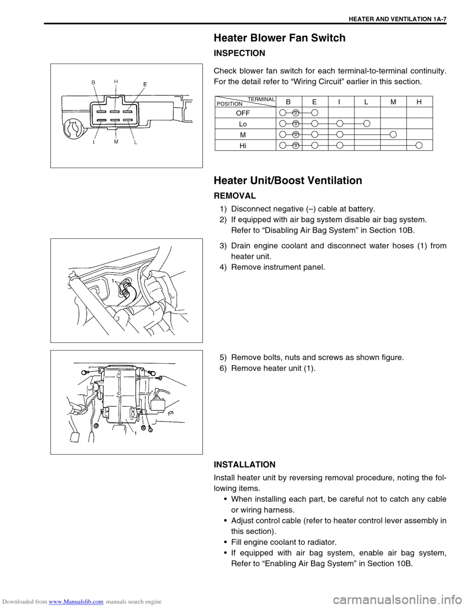
Check blower fan switch for each terminal-to-terminal continuity.
For the detail refer to “Wiring Circuit” earlier in this section.
Heater Unit/Boost Ventilation
REMOVAL
1) Disconnect negative (–) cable at battery.
2) If equipped with air bag system disable air bag system.
Refer to “Disabling Air Bag System” in Section 10B.
3) Drain engine coolant and disconnect water hoses (1) from
heater unit.
4) Remove instrument panel.
5) Remove bolts, nuts and screws as shown figure.
6) Remove heater unit (1).
INSTALLATION
Install heater unit by reversing removal procedure, noting the fol-
lowing items.
When installing each part, be careful not to catch any cable
or wiring harness.
Adjust control cable (refer to heater control lever assembly in
this section).
Fill engine coolant to radiator.
If equipped with air bag system, enable air bag system,
Refer to “Enabling Air Bag System” in Section 10B.
TERMINAL
POSITIONBEI L MH
OFF
Lo
M
Hi
Page 71 of 687

Downloaded from www.Manualslib.com manuals search engine 1B-10 AIR CONDITIONING (OPTIONAL)
Performance Diagnosis
1) Confirm that vehicle and environmental conditions are as fol-
lows.
Vehicle is not exposed to direct sun.
Ambient temperature is within 15 – 35 °C (59 – 95 °F).
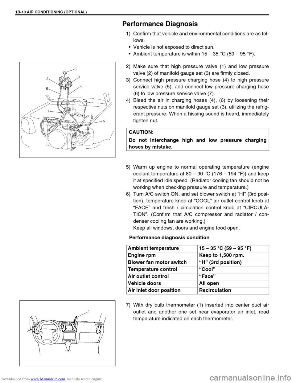
2) Make sure that high pressure valve (1) and low pressure
valve (2) of manifold gauge set (3) are firmly closed.
3) Connect high pressure charging hose (4) to high pressure
service valve (5), and connect low pressure charging hose
(6) to low pressure service valve (7).
4) Bleed the air in charging hoses (4), (6) by loosening their
respective nuts on manifold gauge set (3), utilizing the refrig-
erant pressure. When a hissing sound is heard, immediately
tighten nut.
5) Warm up engine to normal operating temperature (engine
coolant temperature at 80 – 90 °C (176 – 194 °F)) and keep
it at specified idle speed. (Radiator cooling fan should not be
working when checking pressure and temperature.)
6) Turn A/C switch ON, and set blower switch at “HI” (3rd posi-
tion), temperature knob at “COOL” air outlet control knob at
“FACE” and fresh / circulation control knob at “CIRCULA-
TION”. (Confirm that A/C compressor and radiator / con-
denser cooling fan are working.)
Keep all windows, doors and engine food open.
Performance diagnosis condition
7) With dry bulb thermometer (1) inserted into center duct air
outlet and another one set near evaporator air inlet, read
temperature indicated on each thermometer. CAUTION:
Do not interchange high and low pressure charging
hoses by mistake.
Ambient temperature 15 – 35 °C (59 – 95 °F)
Engine rpm Keep to 1,500 rpm.
Blower fan motor switch “H” (3rd position)
Temperature control “Cool”
Air outlet control “Face”
Vehicle doors All open
Air inlet door position Recirculation
Page 92 of 687

Downloaded from www.Manualslib.com manuals search engine AIR CONDITIONING (OPTIONAL) 1B-31
Condenser Assembly
INSPECTION
Check the following.
Check clog of condenser fins.
If, any clogs are found, condenser fins should be washed
with water, and should be dried with compressed air.
Check condenser fins for leakage and breakage.
If any defects are found, repair or replace condenser.
Check condenser fittings for leakage.
If any defects are found, repair or replace condenser.
REMOVAL
1) Disconnect negative (–) cable at battery.
2) Recover refrigerant from A/C system by referring to “Recov-
ery” in this section.
3) Remove front bumper referring to “Front Bumper” in Section
8.
4) Disconnect A/C condenser cooling fan motor and dual pres-
sure switch connectors.
5) Remove radiator mounting bolts.
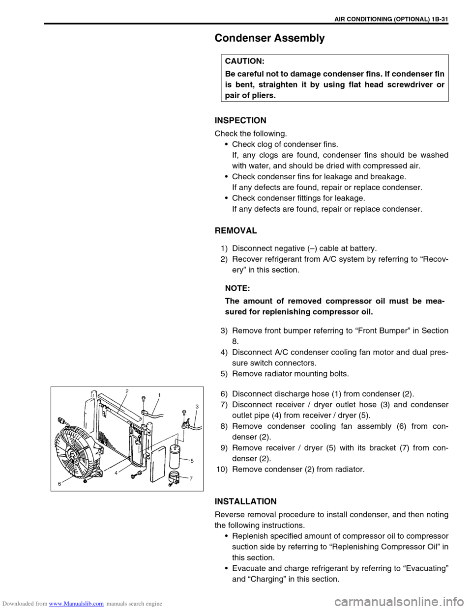
6) Disconnect discharge hose (1) from condenser (2).
7) Disconnect receiver / dryer outlet hose (3) and condenser
outlet pipe (4) from receiver / dryer (5).
8) Remove condenser cooling fan assembly (6) from con-
denser (2).
9) Remove receiver / dryer (5) with its bracket (7) from con-
denser (2).
10) Remove condenser (2) from radiator.
INSTALLATION
Reverse removal procedure to install condenser, and then noting
the following instructions.
Replenish specified amount of compressor oil to compressor
suction side by referring to “Replenishing Compressor Oil” in
this section.
Evacuate and charge refrigerant by referring to “Evacuating”
and “Charging” in this section. CAUTION:
Be careful not to damage condenser fins. If condenser fin
is bent, straighten it by using flat head screwdriver or
pair of pliers.
NOTE:
The amount of removed compressor oil must be mea-
sured for replenishing compressor oil.
Page 94 of 687

Downloaded from www.Manualslib.com manuals search engine AIR CONDITIONING (OPTIONAL) 1B-33
Condenser Cooling Fan Assembly
ASSEMBLY
INSPECTION
1) Check continuity between each two terminals about the con-
denser cooling fan motor (1).
If check results are no continuity, replace condenser cooling
fan motor.
2) Connect battery to condenser cooling fan motor as shown in
figure, then check that the condenser cooling fan motor
operates smoothly.
Reference current of condenser cooling fan motor
approximately 7.5 A at 12 V
REMOVAL
1) Remove front bumper.
2) Disconnect condenser cooling fan motor connector (1).
3) Remove radiator mounting bolts.
4) Remove condenser cooling fan assembly (2) from con-
denser (3).
INSTALLATION
Reverse removal procedure for installation.CAUTION:
Be careful not to damage condenser fins. If condenser fin
is bent, straighten condenser fin by using flat head
screwdriver or pair of pliers.
Page 97 of 687

Downloaded from www.Manualslib.com manuals search engine 1B-36 AIR CONDITIONING (OPTIONAL)
INSTALLATION
Reverse removal procedure to install cooling unit, and then noting
the following instructions.
If A/C evaporator thermistor removed, its should be rein-
stalled in original position.
Install uniformly the packing (1) to installation hole.
Replenish specified amount of compressor oil to compressor
suction side by referring to “Replenishing Compressor Oil” in
this section.
Evacuate and charge refrigerant by referring to “Evacuating”
and “Charging” in this section.
Adjust mode control cable, temperature control cable and
fresh air control cable by referring to “Heater Control Lever
Assembly” in Section 1A.
Enable air bag system referring to “Enable Air Bag System”
in Section 10B. (if equipped)
Fill engine coolant to radiator, referring to “Cooling System
Flush and Refill” in Section 6B.