2005 SUZUKI JIMNY height
[x] Cancel search: heightPage 11 of 687

Downloaded from www.Manualslib.com manuals search engine 0A-6 GENERAL INFORMATION
CAUTION:
Even when the accident was light enough not to cause air bags to activate, be sure to inspect sys-
tem parts and other related parts according to instructions under “Repair and Inspection Required
after an Accident” in Section 10B.
When servicing parts other than air bag system, if shocks may be applied to air bag system compo-
nent parts, remove those parts beforehand.
When handling the air bag (inflator) modules (driver and passenger), seat belt pretensioners (driver
and passenger) or SDM, be careful not to drop it or apply an impact to it. If an excessive impact was
applied (e.g., dropped from a height of 90 cm (3 feet) or more), never attempt disassembly or repair
but replace it with a new one.
When grease, cleaning agent, oil, water, etc. has got onto air bag (inflator) modules (driver and pas-
senger) or seat belt pretensioners (drive and passenger), wipe off immediately with a dry cloth.
Air bag wire harness can be identified easily as it is covered with a yellow protection tube. Be very
careful when handling it.
When an open in air bag wire harness, damaged wire harness, connector or terminal is found,
replace wire harness, connectors and terminals as an assembly.
Do not apply power to the air bag system unless all components are connected or a diagnostic
chart requests it, as this will set a diagnostic trouble code.
Never use air bag system component parts from another vehicle.
When using electric welding, be sure to disconnect air bag (inflator) module connectors (driver and
passenger) and seat belt pretensioner connectors (driver and passenger) respectively.
Never expose air bag system component parts directly to hot air (drying or baking the vehicle after
painting) or flames.
WARNING / CAUTION labels are attached on each part of air bag system components. Be sure to
follow the instructions.
After vehicle is completely repaired, perform “Air Bag Diagnostic System Check” in Section 10B.
Page 34 of 687

Downloaded from www.Manualslib.com manuals search engine MAINTENANCE AND LUBRICATION 0B-3
IntervalKm (x 1,000) 153045607590
Miles (x 1,000) 9 18 27 36 45 54
Months 12 24 36 48 60 72
CHASSIS AND BODY
Clutch (pedal height and travel)–I–I–I
Brake discs and pads (thickness, wear, damage) I I I I I I
Brake drums and shoes (wear, damage)–I–I–I
Brake hoses and pipes (leakage, damage, clamp)–I–I–I
Brake fluid–R–R–R
Brake lever and cable (damage, stroke, operation) Inspect at first 15,000 km (9,000 miles) only.
Tires (wear, damage, rotation) I I I I I I
Wheel discs (damage) I I I I I I
Suspension system (tightness, damage, rattle, breakage)–I–I–I
Propeller shafts––I––I
Manual transmission oil (leakage, level) (I: 1st 15,000 km only) I–R––R
Automatic transmission Fluid level–I–I–I
Fluid change Replace every 165,000 km (99,000 miles).
Fluid hose–––R––
Transfer oil (leakage, level) I–I–I–
Differential oil (leakage, level) (R: 1st 15,000 km only) R or I–I–I–
Steering system (tightness, damage, breakage, rattle)–I–I–I
Power steering (if equipped) I I I I I I
All latches, hinges and locks–I–I–I
NOTE:
“R”: Replace or change
“I”: Inspect and correct, replace or lubricate if necessary
Page 42 of 687

Downloaded from www.Manualslib.com manuals search engine MAINTENANCE AND LUBRICATION 0B-11
PCV (Positive Crankcase Ventilation) Valve
INSPECTION
Check crankcase ventilation hose and PCV hose for leaks, cracks
or clog, and PCV valve for stick or clog. Refer to “PCV System” of
Section 6E for PCV valve checking procedure.
Fuel Evaporative Emission Control System
INSPECTION
1) Visually inspect hoses for cracks, damage, or excessive
bends. Inspect all clamps for damage and proper position.
2) Check EVAP canister for operation and clog, referring to
“Evaporative Emission (EVAP) Control System” in Section
6E.
If a malfunction is found, repair or replace.
Chassis and Body
Clutch
INSPECTION
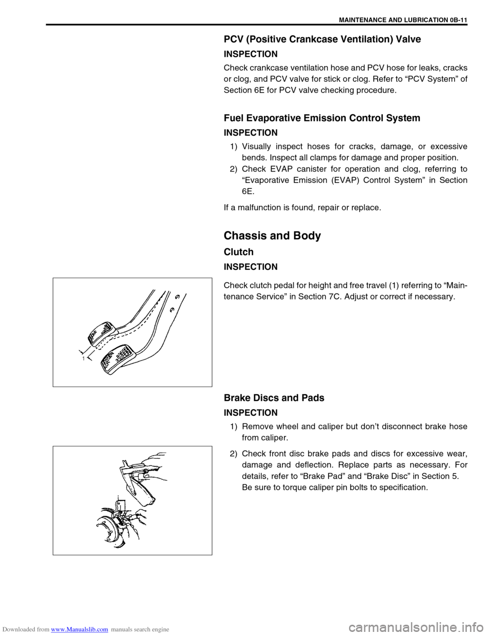
Check clutch pedal for height and free travel (1) referring to “Main-
tenance Service” in Section 7C. Adjust or correct if necessary.
Brake Discs and Pads
INSPECTION
1) Remove wheel and caliper but don’t disconnect brake hose
from caliper.
2) Check front disc brake pads and discs for excessive wear,
damage and deflection. Replace parts as necessary. For
details, refer to “Brake Pad” and “Brake Disc” in Section 5.
Be sure to torque caliper pin bolts to specification.
Page 120 of 687

Downloaded from www.Manualslib.com manuals search engine FRONT WHEEL ALIGNMENT 3A-3
Diagnosis
Diagnosis Table
For the details, refer to “Diagnosis Table” in Section 3.
Preliminary Checks Prior To Adjusting Front Wheel Alignment
Steering and vibration complaints are not always the result of improper alignment. An additional item to be
checked is the possibility of tire lead due to worn or improperly manufactured tires. “Lead” is the deviation of the
vehicle from a straight path on a level road without hand pressure on the steering wheel. Section 3 of this man-
ual contains a procedure for determining the presence of a tire lead problem. Before making any adjustment
affecting toe setting, the following checks and inspections should be made to ensure correctness of alignment
readings and alignment adjustments:
1) Check all tires for proper inflation pressures and approximately the same tread wear.
2) Check for loose of king pin bearings. Check tie rod ends; if excessive looseness is noted, it must be cor-
rected before adjusting.
3) Check for run-out of wheels and tires.
4) Check vehicle trim heights; if out of limits and a correction is to be made, it must be made before adjusting
toe.
5) Check for loose of suspension arms.
6) Check for loose or missing stabilizer bar attachments.
7) Consideration must be given to excess loads, such as tool boxes. If this excess load is normally carried in
vehicle, it should remain in vehicle during alignment checks.
8) Consider condition of equipment being used to check alignment and follow manufacturer's instructions.
9) Regardless of equipment used to check alignment, vehicle must be on a level surface both fore and aft and
transversely.
Toe Adjustment
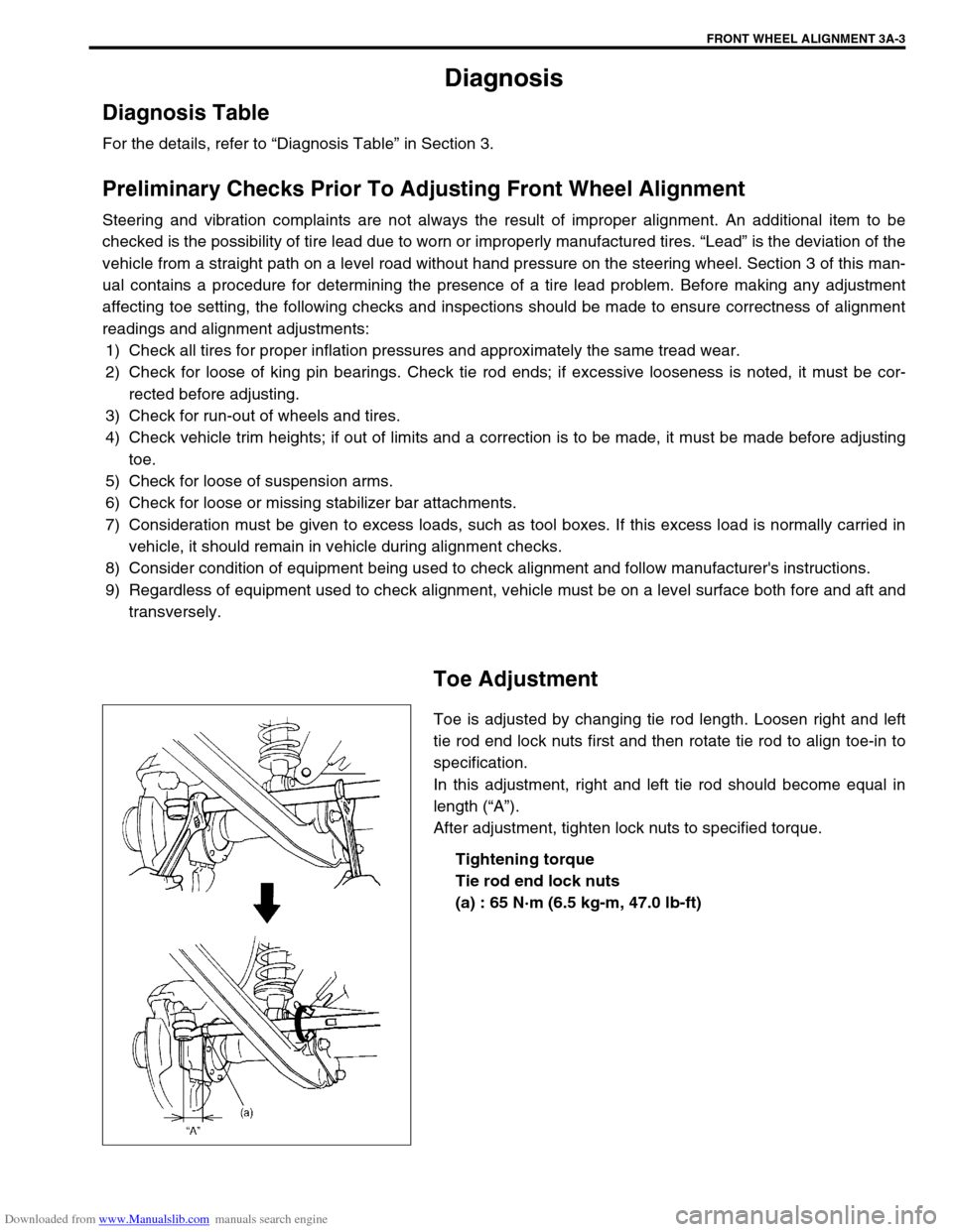
Toe is adjusted by changing tie rod length. Loosen right and left
tie rod end lock nuts first and then rotate tie rod to align toe-in to
specification.
In this adjustment, right and left tie rod should become equal in
length (“A”).
After adjustment, tighten lock nuts to specified torque.
Tightening torque
Tie rod end lock nuts
(a) : 65 N·m (6.5 kg-m, 47.0 lb-ft)
Page 157 of 687

Downloaded from www.Manualslib.com manuals search engine 3C-4 STEERING WHEEL AND COLUMN
Drive Air Bag (Inflator) Module (For Vehicle
with Air Bag System)
REMOVAL
1) Disconnect negative battery cable at battery terminal.
2) Disable air bag system. Refer to “Disabling Air Bag System”
in Section 10B.
3) Remove steering wheel side cap (1) of left side.
4) Loosen 2 bolts (2) mounting driver air bag (inflator) module
till it turns freely, pull them out and fix them to bolt clamps (3).
5) Remove driver air bag (inflator) module (1) from steering
wheel.
6) Disconnect yellow connector (2) in order a) – b) as shown.
INSPECTION
WARNING:
When handling an air bag (inflator) module, be sure to
read “Service Precautions” given earlier in this section
and observe each instruction. Failure to follow them
could cause a damage to the air bag (inflator) module or
result in personal injury.
WARNING:
Never disassemble driver air bag (inflator) module or
measure its resistance. Otherwise, personal injury may
result.
CAUTION:
If air bag (inflator) module was dropped from a height of
90 cm (3 ft) or more, it should be replaced.
Page 262 of 687

Downloaded from www.Manualslib.com manuals search engine BRAKES 5-1
6F1
6F2
6G
6H
6K
7A
7A1
7B1
7C1
7D
7E
5
9
10
10A
10B
9
10
10A
10B
SECTION 5
BRAKES
CONTENTS
General Description ......................................... 5-3
Diagnosis .......................................................... 5-4
Road Testing Brakes ...................................... 5-4
Brake Fluid Leaks .......................................... 5-4
Substandard or Contaminated Brake Fluid .... 5-4
Diagnosis Table ............................................. 5-5
Brake Pedal Free Height Adjustment ............. 5-8
Brake Pedal Play Check ................................ 5-8
Stop Light Switch Adjustment ........................ 5-8
Excessive Pedal Travel Check ....................... 5-9
Front Brake Disc Check ................................. 5-9
Front Brake Pad Check .................................. 5-9
Rear Brake Shoe Check .............................. 5-10
Master Cylinder and Brake Fluid Level
Check ........................................................... 5-10
Rear Drum Brake Shoe Adjustment ............. 5-11
Parking Brake Inspection and Adjustment ... 5-11
Booster Operation Check ............................. 5-12Fluid Pressure Test
(If Equipped with LSPV) ............................... 5-15
On-Vehicle Service ........................................ 5-17
Air Bleeding of Brake System ...................... 5-17
Brake Hose and Pipe Inspection.................. 5-18
Front Disc Brake .......................................... 5-19
Brake pad ................................................. 5-20
Caliper assembly...................................... 5-22
Brake Disc.................................................... 5-26
Rear Brake ................................................... 5-29
Brake drum............................................... 5-29
Brake shoe ............................................... 5-32
Wheel Cylinder............................................. 5-33
Brake back plate ...................................... 5-34
Master Cylinder .............................................. 5-36
Master Cylinder Reservoir ........................... 5-36
Master Cylinder Assembly ........................... 5-37 WARNING:
For lifting point of vehicle, refer to Section 0A.
WARNING:
For vehicles equipped with Supplement Restraint (Air Bag) System:
Service on and around the air bag system components or wiring must be performed only by an
authorized SUZUKI dealer. Refer to “Air Bag System Components and Wiring Location View” under
“General Description” in air bag system section in order to confirm whether you are performing ser-
vice on or near the air bag system components or wiring. Please observe all WARNINGS and “Ser-
vice Precautions” under “On-Vehicle Service” in air bag system section before performing service
on or around the air bag system components or wiring. Failure to follow WARNINGS could result in
unintentional activation of the system or could render the system inoperative. Either of these two
conditions may result in severe injury.
Technical service work must be started at least 90 seconds after the ignition switch is turned to the
“LOCK” position and the negative cable is disconnected from the battery. Otherwise, the system
may be activated by reserve energy in the Sensing and Diagnostic Module (SDM).
NOTE:
When inspecting and servicing vehicle equipped with ABS, be sure to refer to section 5E first.
All brake fasteners are important attaching parts in that they could affect the performance of vital
parts and systems, and/or could result in major repair expense. They must be replaced with one of
same part number or with an equivalent part if replacement becomes necessary. Do not use a
replacement part of lesser quality or substitute design. Torque values must be used as specified
during reassembly to assure proper retention of all parts. There is to be no welding as it may result
in extensive damage and weakening of the metal.
Page 269 of 687

Downloaded from www.Manualslib.com manuals search engine 5-8 BRAKES
Brake Pedal Free Height Adjustment
1) Check brake pedal free height.
If it is not within specification, check and adjust following item
2) and 3).
Brake pedal free height “a” from wall
LH steering vehicle : 221 – 227 mm (8.70 – 8.94 in.)
RH steering vehicle : 217 – 223 mm (8.54 – 8.78 in.)
2) Check measurement between booster mounting surface and
center of clevis pin hole. When booster push rod clevis has
been reinstalled, it is important that the measurement is
adjusted. (Refer to “Brake Booster Inspection and Adjust-
ment” in this section.)
3) Check stop light switch position. Adjust it if it is out of specifi-
cation.
Brake Pedal Play Check
Pedal play should be within specification below.
If out of specification, check stop light switch for proper installation
position and adjust if necessary.
Also check pedal shaft bolt and master cylinder pin installation for
looseness and replace if defective.
Brake pedal play “a” : 1 – 8 mm (0.04 – 0.31 in.)
Stop Light Switch Adjustment
Adjustment should be made as follows when installing switch. Pull
up brake pedal toward you and while holding it there, adjust
switch position so that clearance between end of thread and
brake pedal is specified. Then tighten lock nut to specified torque.
Clearance between brake pedal and stop light switch
“c” : 1.5 – 2.0 mm (0.06 – 0.08 in.)
Tightening torque
Stop light switch lock nut
(a) : 6.5 N·m (0.65 kg-m, 4.7 lb-ft)
Page 275 of 687

Downloaded from www.Manualslib.com manuals search engine 5-14 BRAKES
CHECK AIR TIGHTNESS UNDER LOAD
1) With engine running, depress brake pedal. Then stop engine
while holding brake pedal depressed.
2) Hold brake pedal depressed for 30 seconds. If pedal height
does not change, condition is good. But it isn’t if pedal rises.
H : Hold
H : Hold
T : 30 seconds