Page 299 of 687
Downloaded from www.Manualslib.com manuals search engine 5-38 BRAKES
INSTALLATION
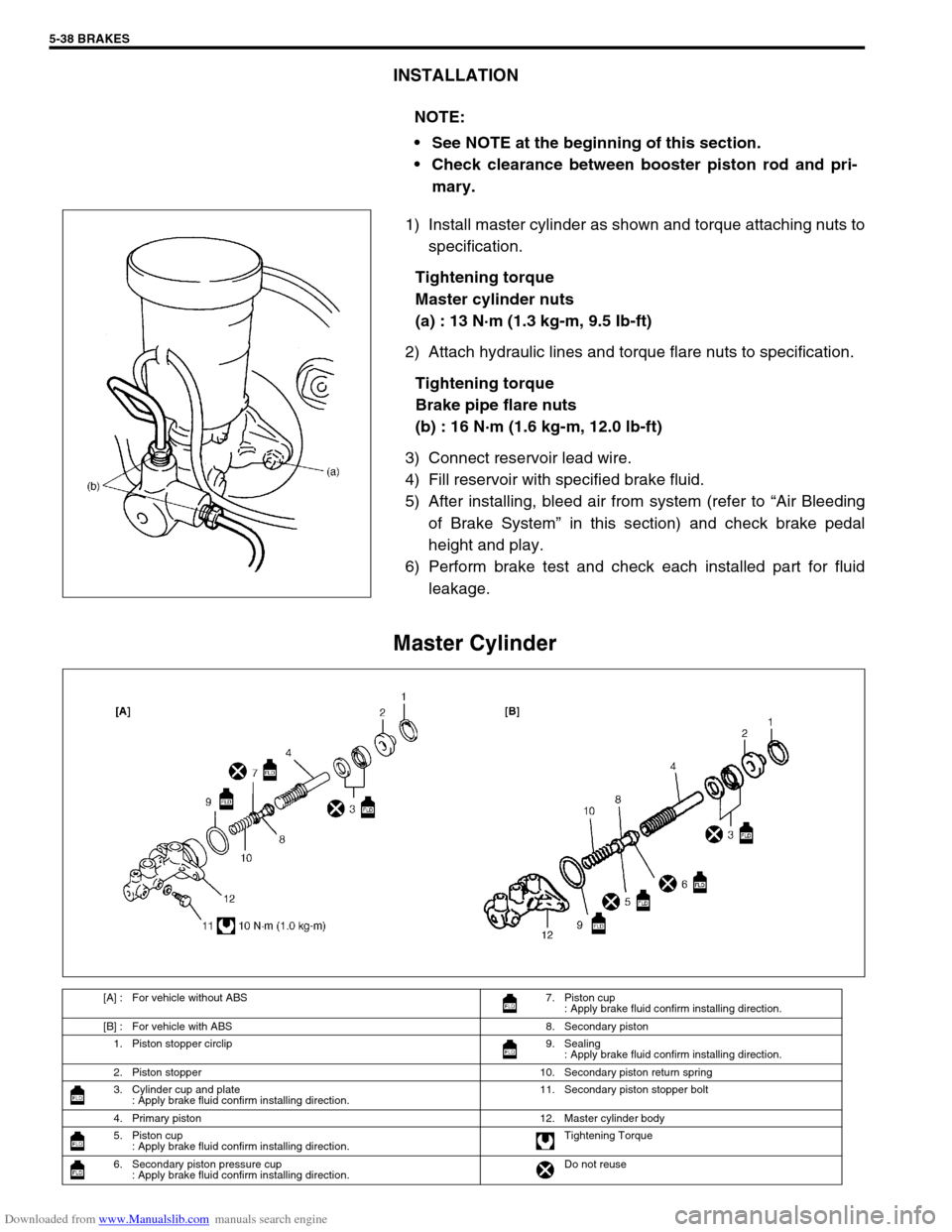
1) Install master cylinder as shown and torque attaching nuts to
specification.
Tightening torque
Master cylinder nuts
(a) : 13 N·m (1.3 kg-m, 9.5 Ib-ft)
2) Attach hydraulic lines and torque flare nuts to specification.
Tightening torque
Brake pipe flare nuts
(b) : 16 N·m (1.6 kg-m, 12.0 lb-ft)
3) Connect reservoir lead wire.
4) Fill reservoir with specified brake fluid.
5) After installing, bleed air from system (refer to “Air Bleeding
of Brake System” in this section) and check brake pedal
height and play.
6) Perform brake test and check each installed part for fluid
leakage.
Master Cylinder
NOTE:
See NOTE at the beginning of this section.
Check clearance between booster piston rod and pri-
mary.
[A] : For vehicle without ABS 7. Piston cup
: Apply brake fluid confirm installing direction.
[B] : For vehicle with ABS 8. Secondary piston
1. Piston stopper circlip 9. Sealing
: Apply brake fluid confirm installing direction.
2. Piston stopper 10. Secondary piston return spring
3. Cylinder cup and plate
: Apply brake fluid confirm installing direction.11. Secondary piston stopper bolt
4. Primary piston 12. Master cylinder body
5. Piston cup
: Apply brake fluid confirm installing direction.Tightening Torque
6. Secondary piston pressure cup
: Apply brake fluid confirm installing direction.Do not reuse
Page 507 of 687
Downloaded from www.Manualslib.com manuals search engine 6A1-26 ENGINE MECHANICAL (M13 ENGINE)
INSTALLATION
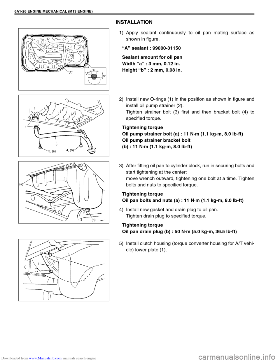
1) Apply sealant continuously to oil pan mating surface as
shown in figure.
“A” sealant : 99000-31150
Sealant amount for oil pan
Width “a” : 3 mm, 0.12 in.
Height “b” : 2 mm, 0.08 in.
2) Install new O-rings (1) in the position as shown in figure and
install oil pump strainer (2).
Tighten strainer bolt (3) first and then bracket bolt (4) to
specified torque.
Tightening torque
Oil pump strainer bolt (a) : 11 N·m (1.1 kg-m, 8.0 lb-ft)
Oil pump strainer bracket bolt
(b) : 11 N·m (1.1 kg-m, 8.0 lb-ft)
3) After fitting oil pan to cylinder block, run in securing bolts and
start tightening at the center:
move wrench outward, tightening one bolt at a time. Tighten
bolts and nuts to specified torque.
Tightening torque
Oil pan bolts and nuts (a) : 11 N·m (1.1 kg-m, 8.0 lb-ft)
4) Install new gasket and drain plug to oil pan.
Tighten drain plug to specified torque.
Tightening torque
Oil pan drain plug (b) : 50 N·m (5.0 kg-m, 36.5 lb-ft)
5) Install clutch housing (torque converter housing for A/T vehi-
cle) lower plate (1).
Page 512 of 687
Downloaded from www.Manualslib.com manuals search engine ENGINE MECHANICAL (M13 ENGINE) 6A1-31
INSPECTION
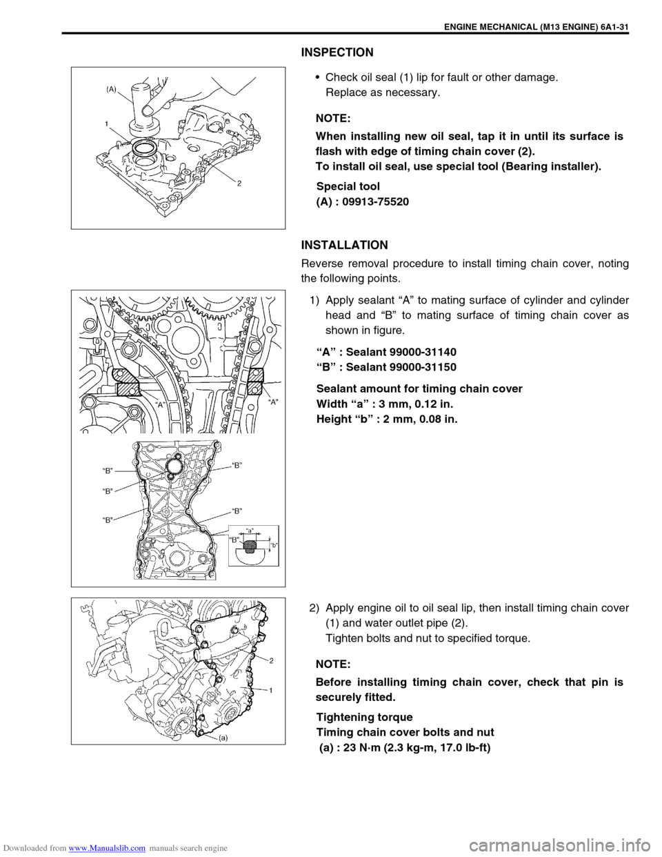
Check oil seal (1) lip for fault or other damage.
Replace as necessary.
Special tool
(A) : 09913-75520
INSTALLATION
Reverse removal procedure to install timing chain cover, noting
the following points.
1) Apply sealant “A” to mating surface of cylinder and cylinder
head and “B” to mating surface of timing chain cover as
shown in figure.
“A” : Sealant 99000-31140
“B” : Sealant 99000-31150
Sealant amount for timing chain cover
Width “a” : 3 mm, 0.12 in.
Height “b” : 2 mm, 0.08 in.
2) Apply engine oil to oil seal lip, then install timing chain cover
(1) and water outlet pipe (2).
Tighten bolts and nut to specified torque.
Tightening torque
Timing chain cover bolts and nut
(a) : 23 N·m (2.3 kg-m, 17.0 lb-ft) NOTE:
When installing new oil seal, tap it in until its surface is
flash with edge of timing chain cover (2).
To install oil seal, use special tool (Bearing installer).
NOTE:
Before installing timing chain cover, check that pin is
securely fitted.
Page 524 of 687
Downloaded from www.Manualslib.com manuals search engine ENGINE MECHANICAL (M13 ENGINE) 6A1-43
7) Remove tappets (1) with shims (2).
INSPECTION
Cam Wear
Using a micrometer, measure cam height “a”. If measured height
is below its limit, replace camshaft.
Cam height “a” of camshaft
Camshaft Runout
Set camshaft between two “V” blocks, and measure its runout by
using a dial gauge.
If measured runout exceeds below limit, replace camshaft.
Camshaft runout limit
0.10 mm (0.0039 in.)
Camshaft Journal Wear
Check camshaft journals and camshaft housings for pitting,
scratches, wear or damage.
If any malcondition is found, replace camshaft or cylinder head
with housing. Never replace cylinder head without replacing
housings.
Standard Limit
Intake cam 44.919 – 45.079 mm
(1.768 – 1.775 in.)44.80 mm
(1.764 in.)
Exhaust cam 44.399 – 44.559 mm
(1.748 – 1.754 in.)44.28 mm
(1.743 in.)
Page 572 of 687
Downloaded from www.Manualslib.com manuals search engine ENGINE MECHANICAL (M13 ENGINE) 6A1-91
5) Install crankshaft to cylinder block.
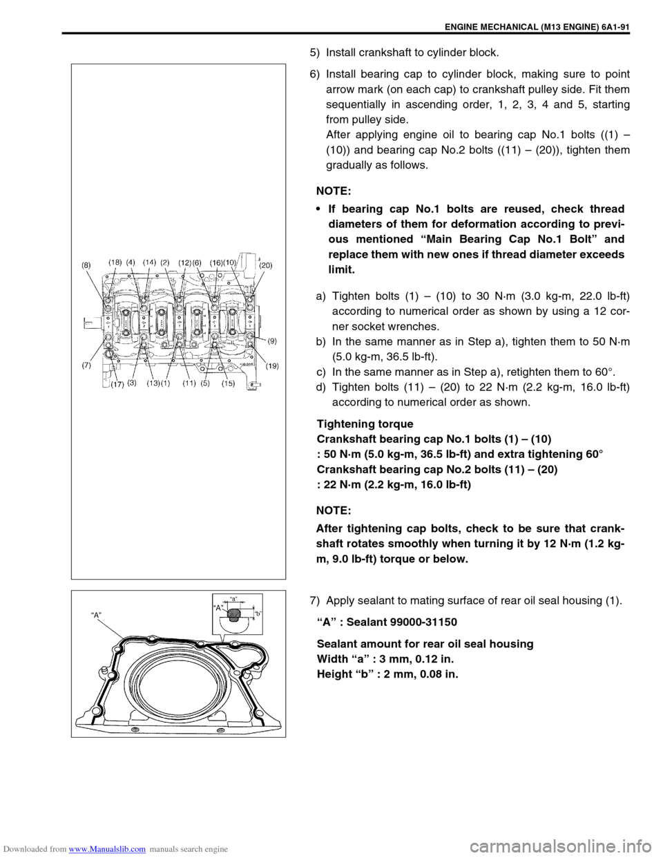
6) Install bearing cap to cylinder block, making sure to point
arrow mark (on each cap) to crankshaft pulley side. Fit them
sequentially in ascending order, 1, 2, 3, 4 and 5, starting
from pulley side.
After applying engine oil to bearing cap No.1 bolts ((1) –
(10)) and bearing cap No.2 bolts ((11) – (20)), tighten them
gradually as follows.
a) Tighten bolts (1) – (10) to 30 N·m (3.0 kg-m, 22.0 lb-ft)
according to numerical order as shown by using a 12 cor-
ner socket wrenches.
b) In the same manner as in Step a), tighten them to 50 N·m
(5.0 kg-m, 36.5 lb-ft).
c) In the same manner as in Step a), retighten them to 60°.
d) Tighten bolts (11) – (20) to 22 N·m (2.2 kg-m, 16.0 lb-ft)
according to numerical order as shown.
Tightening torque
Crankshaft bearing cap No.1 bolts (1) – (10)
: 50 N·m (5.0 kg-m, 36.5 lb-ft) and extra tightening 60°
Crankshaft bearing cap No.2 bolts (11) – (20)
: 22 N·m (2.2 kg-m, 16.0 lb-ft)
7) Apply sealant to mating surface of rear oil seal housing (1).
“A” : Sealant 99000-31150
Sealant amount for rear oil seal housing
Width “a” : 3 mm, 0.12 in.
Height “b” : 2 mm, 0.08 in. NOTE:
If bearing cap No.1 bolts are reused, check thread
diameters of them for deformation according to previ-
ous mentioned “Main Bearing Cap No.1 Bolt” and
replace them with new ones if thread diameter exceeds
limit.
NOTE:
After tightening cap bolts, check to be sure that crank-
shaft rotates smoothly when turning it by 12 N·m (1.2 kg-
m, 9.0 lb-ft) torque or below.
Page 593 of 687
Downloaded from www.Manualslib.com manuals search engine 6B-16 ENGINE COOLING
INSPECTION
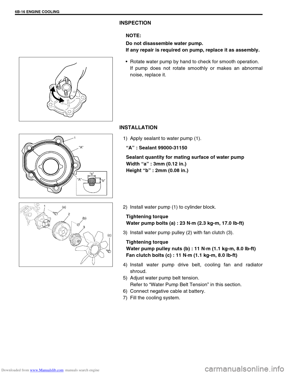
Rotate water pump by hand to check for smooth operation.
If pump does not rotate smoothly or makes an abnormal
noise, replace it.
INSTALLATION
1) Apply sealant to water pump (1).
“A” : Sealant 99000-31150
Sealant quantity for mating surface of water pump
Width “a” : 3mm (0.12 in.)
Height “b” : 2mm (0.08 in.)
2) Install water pump (1) to cylinder block.
Tightening torque
Water pump bolts (a) : 23 N·m (2.3 kg-m, 17.0 lb-ft)
3) Install water pump pulley (2) with fan clutch (3).
Tightening torque
Water pump pulley nuts (b) : 11 N·m (1.1 kg-m, 8.0 lb-ft)
Fan clutch bolts (c) : 11 N·m (1.1 kg-m, 8.0 lb-ft)
4) Install water pump drive belt, cooling fan and radiator
shroud.
5) Adjust water pump belt tension.
Refer to “Water Pump Belt Tension” in this section.
6) Connect negative cable at battery.
7) Fill the cooling system.NOTE:
Do not disassemble water pump.
If any repair is required on pump, replace it as assembly.
Page 620 of 687
Downloaded from www.Manualslib.com manuals search engine ENGINE AND EMISSION CONTROL SYSTEM 6E-15
On-Vehicle Service
Accelerator cable adjustment
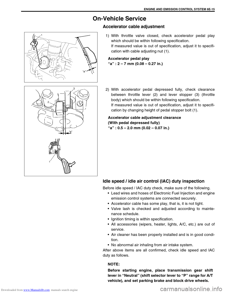
1) With throttle valve closed, check accelerator pedal play
which should be within following specification.
If measured value is out of specification, adjust it to specifi-
cation with cable adjusting nut (1).
Accelerator pedal play
“a” : 2 – 7 mm (0.08 – 0.27 in.)
2) With accelerator pedal depressed fully, check clearance
between throttle lever (2) and lever stopper (3) (throttle
body) which should be within following specification.
If measured value is out of specification, adjust it to specifi-
cation by changing height of pedal stopper bolt (1).
Accelerator cable adjustment clearance
(With pedal depressed fully)
“a” : 0.5 – 2.0 mm (0.02 – 0.07 in.)
Idle speed / idle air control (IAC) duty inspection
Before idle speed / IAC duty check, make sure of the following.
Lead wires and hoses of Electronic Fuel Injection and engine
emission control systems are connected securely.
Accelerator cable has some play, that is, it is not tight.
Valve lash is checked and adjusted according to mainte-
nance schedule.
Ignition timing is within specification.
All accessories (wipers, heater, lights, A/C, etc.) are out of
service.
Air cleaner has been properly installed and is in good condi-
tion.
No abnormal air inhaling from air intake system.
After above items are all confirmed, check idle speed and IAC
duty as follows.
NOTE:
Before starting engine, place transmission gear shift
lever in “Neutral” (shift selector lever to “P” range for A/T
vehicle), and set parking brake and block drive wheels.