2005 SUZUKI JIMNY Thermostat
[x] Cancel search: ThermostatPage 382 of 687

Downloaded from www.Manualslib.com manuals search engine ENGINE GENERAL INFORMATION AND DIAGNOSIS 6-25
Excessive detonation
(The engine makes
sharp metallic knocks
that change with throt-
tle opening.
Sounds like pop corn
popping.)Engine overheating Refer to “Overheating” of this table.
Faulty spark plug Spark plugs in Section 6F.
Clogged fuel filter and fuel lines Diagnostic Flow Table B-3
Malfunctioning EGR valve (if equipped) EGR system in Section 6E.
Poor performance of knock sensor, ECT
sensor or MAP sensorKnock sensor in this section, ECT
sensor or MAP sensor in Section 6E.
Faulty injector Diagnostic Flow Table B-1
Faulty ECM Inspection of ECM and its circuit in
this section.
Excessive combustion chamber deposits Piston and cylinder head in Section
6A1.
Overheating
Inoperative thermostat Thermostat in Section 6B.
Faulty A/C condenser fan motor or its cir-
cuitA/C condenser fan control system
check in Section 6E.
Loose or slip water pump belt ITEM1-1 Drive belt inspection and
change in Section 0B.
Poor water pump performance Water pump in Section 6B.
Clogged or leaky radiator Radiator in Section 6B.
Improper engine oil grade ITEM1-3 Engine oil and oil filter
change in Section 0B.
Clogged oil filter or oil strainer Oil pressure check in Section 6A1.
Poor oil pump performance Oil pressure check in Section 6A1.
Dragging brakes Diagnosis Table in Section 5.
Slipping clutch Diagnosis Table in Section 7C.
Blown cylinder head gasket Valves and cylinder head in Section
6A1.
Poor gasoline mileage
Faulty ignition coil Ignition coil assembly in Section 6F.
Fuel pressure out of specification Diagnostic Flow Table B-3
Faulty TP sensor, ECT sensor or MAP
sensorTP sensor, ECT sensor or MAP sen-
sor in Section 6E.
Faulty injector Diagnostic Flow Table B-1
Faulty ECM Inspection of ECM and its circuit in
this section.
Malfunctioning EGR valve (if equipped) EGR system in Section 6E.
High idle speed Refer to item “Improper Engine Idle
Speed” previously outlined.
Low compression Previously outlined.
Poor valve seating Valves and cylinder head in Section
6A1.
Dragging brakes Diagnosis Table in Section 5.
Slipping clutch Diagnosis Table in Section 7C.
Thermostat out of order Thermostat in Section 6B.
Improper tire pressure Refer to Section 3F. Condition Possible Cause Reference Item
Page 531 of 687

Downloaded from www.Manualslib.com manuals search engine 6A1-50 ENGINE MECHANICAL (M13 ENGINE)
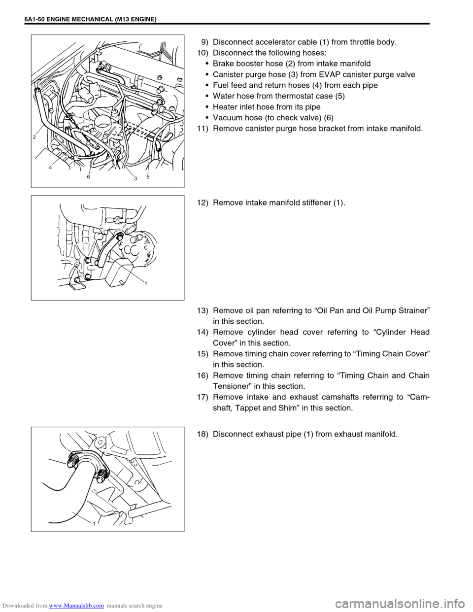
9) Disconnect accelerator cable (1) from throttle body.
10) Disconnect the following hoses:
Brake booster hose (2) from intake manifold
Canister purge hose (3) from EVAP canister purge valve
Fuel feed and return hoses (4) from each pipe
Water hose from thermostat case (5)
Heater inlet hose from its pipe
Vacuum hose (to check valve) (6)
11) Remove canister purge hose bracket from intake manifold.
12) Remove intake manifold stiffener (1).
13) Remove oil pan referring to “Oil Pan and Oil Pump Strainer”
in this section.
14) Remove cylinder head cover referring to “Cylinder Head
Cover” in this section.
15) Remove timing chain cover referring to “Timing Chain Cover”
in this section.
16) Remove timing chain referring to “Timing Chain and Chain
Tensioner” in this section.
17) Remove intake and exhaust camshafts referring to “Cam-
shaft, Tappet and Shim” in this section.
18) Disconnect exhaust pipe (1) from exhaust manifold.
Page 578 of 687

Downloaded from www.Manualslib.com manuals search engine ENGINE COOLING 6B-1
6B
SECTION 6B
ENGINE COOLING
CONTENTS
General Description ........................................6B-2
Cooling System Circulation ........................... 6B-2
Radiator Cap ................................................. 6B-3
Coolant Reservoir ......................................... 6B-3
Water Pump .................................................. 6B-4
Thermostat .................................................... 6B-4
Cooling Fan Clutch ........................................ 6B-4
Coolant (Water) Temperature Gauge............ 6B-4
Diagnosis .........................................................6B-5
Maintenance ....................................................6B-6
Coolant .......................................................... 6B-6
Coolant Level ................................................ 6B-7
Cooling System Service ................................ 6B-7Cooling System Flush and Refill ................... 6B-8
Water Pump Belt Tension ............................. 6B-9
On-Vehicle Service ....................................... 6B-10
Cooling System Component ....................... 6B-10
Coolant Draining ......................................... 6B-11
Cooling Water Pipes or Hoses .................... 6B-11
Thermostat .................................................. 6B-11
Water Pump Belt and Cooling Fan ............. 6B-13
Radiator ...................................................... 6B-14
Water Pump ................................................ 6B-15
Required Service Material ............................ 6B-17
Tightening Torque Specification ................. 6B-17
Page 579 of 687

Downloaded from www.Manualslib.com manuals search engine 6B-2 ENGINE COOLING
General Description
The cooling system consists of the radiator cap, radiator, reservoir, hoses, water pump, cooling fan & clutch,
thermostat. The radiator is of tube-and-fin type.
Cooling System Circulation
1. Radiator inlet hose 5. Water pump 9. Heater outlet hose
2. Radiator outlet hose 6. Fast idle control plunger of throttle body 10. Radiator
3. Water inlet pipe 7. Cylinder block/cylinder head
4. Thermostat 8. Heater inlet hose
Page 581 of 687

Downloaded from www.Manualslib.com manuals search engine 6B-4 ENGINE COOLING
Water Pump
The centrifugal type water pump is used in the cooling system.
The pump impeller is supported by a totally sealed bearing.
The water pump can not be disassembled.
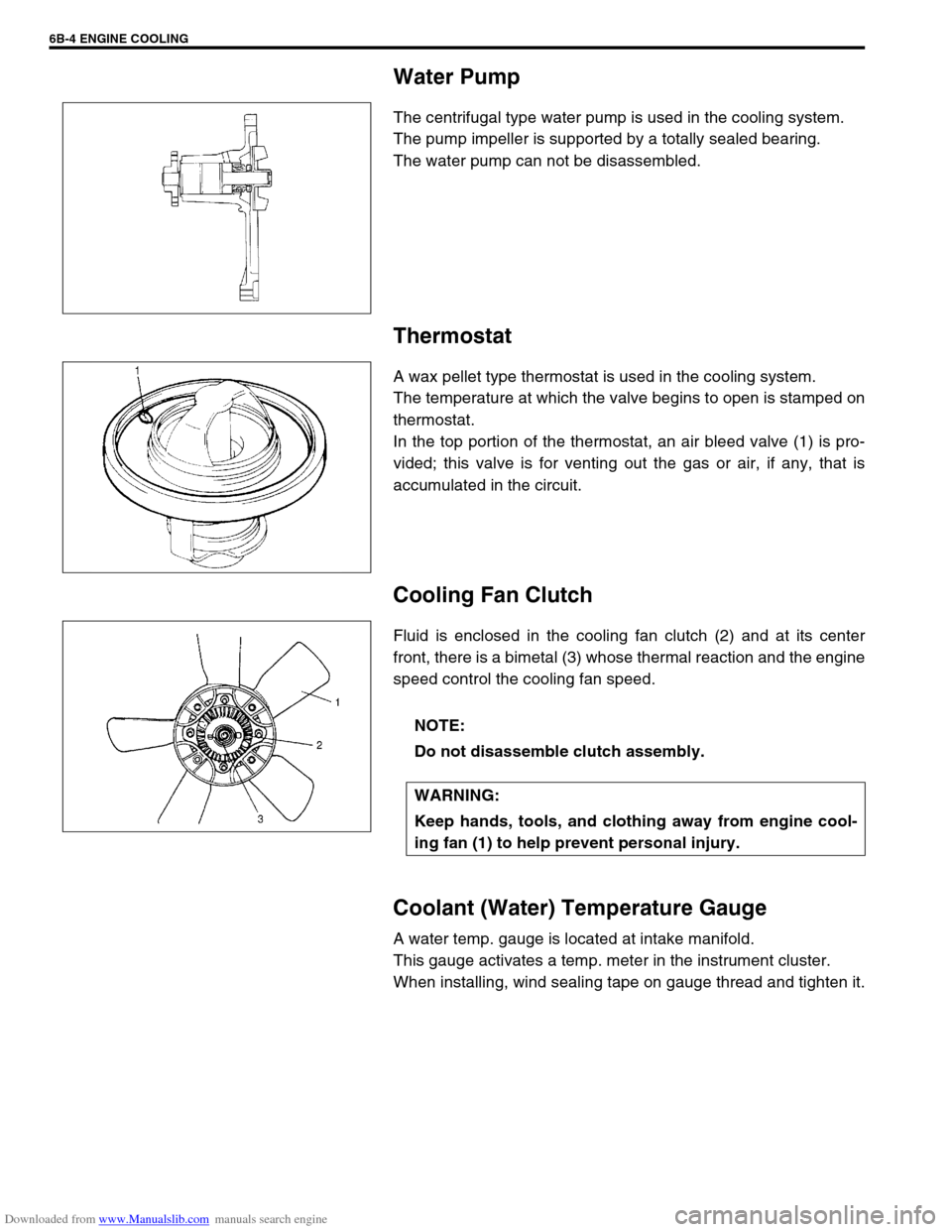
Thermostat
A wax pellet type thermostat is used in the cooling system.
The temperature at which the valve begins to open is stamped on
thermostat.
In the top portion of the thermostat, an air bleed valve (1) is pro-
vided; this valve is for venting out the gas or air, if any, that is
accumulated in the circuit.
Cooling Fan Clutch
Fluid is enclosed in the cooling fan clutch (2) and at its center
front, there is a bimetal (3) whose thermal reaction and the engine
speed control the cooling fan speed.
Coolant (Water) Temperature Gauge
A water temp. gauge is located at intake manifold.
This gauge activates a temp. meter in the instrument cluster.
When installing, wind sealing tape on gauge thread and tighten it.
NOTE:
Do not disassemble clutch assembly.
WARNING:
Keep hands, tools, and clothing away from engine cool-
ing fan (1) to help prevent personal injury.
Page 582 of 687

Downloaded from www.Manualslib.com manuals search engine ENGINE COOLING 6B-5
Diagnosis
Condition Possible Cause Correction
Engine overheats
Loose or broken water pump belt
Not enough coolant
Faulty thermostat
Faulty water pump
Dirty or bent radiator fins
Coolant leakage on cooling system
Defective cooling fan clutch
Plugged radiator
Faulty radiator cap
Maladjusted ignition timing
Dragging brakes
Slipping clutchAdjust or replace.
Check coolant level and add as
necessary.
Replace.
Replace.
Clean or remedy.
Repair.
Check and replace as necessary.
Check and replace radiator as
necessary.
Replace.
Check system related parts.
Adjust brake.
Adjust or replace.
Page 585 of 687

Downloaded from www.Manualslib.com manuals search engine 6B-8 ENGINE COOLING
5) Tighten hose clamps and inspect all hoses.
Replace hoses whenever cracked, swollen or otherwise
deteriorated.
6) Clean frontal area of radiator core.
Cooling System Flush and Refill
1) Remove radiator cap when engine is cool:
Turn cap slowly to the left until it reaches a “stop” (Do not
press down while turning it).
Wait until pressure is relieved (indicated by a hissing sound)
then press down on cap and continue to turn it to the left.
2) With radiator cap removed, run engine until upper radiator
hose is hot (this shows that thermostat is open and coolant is
flowing through system).
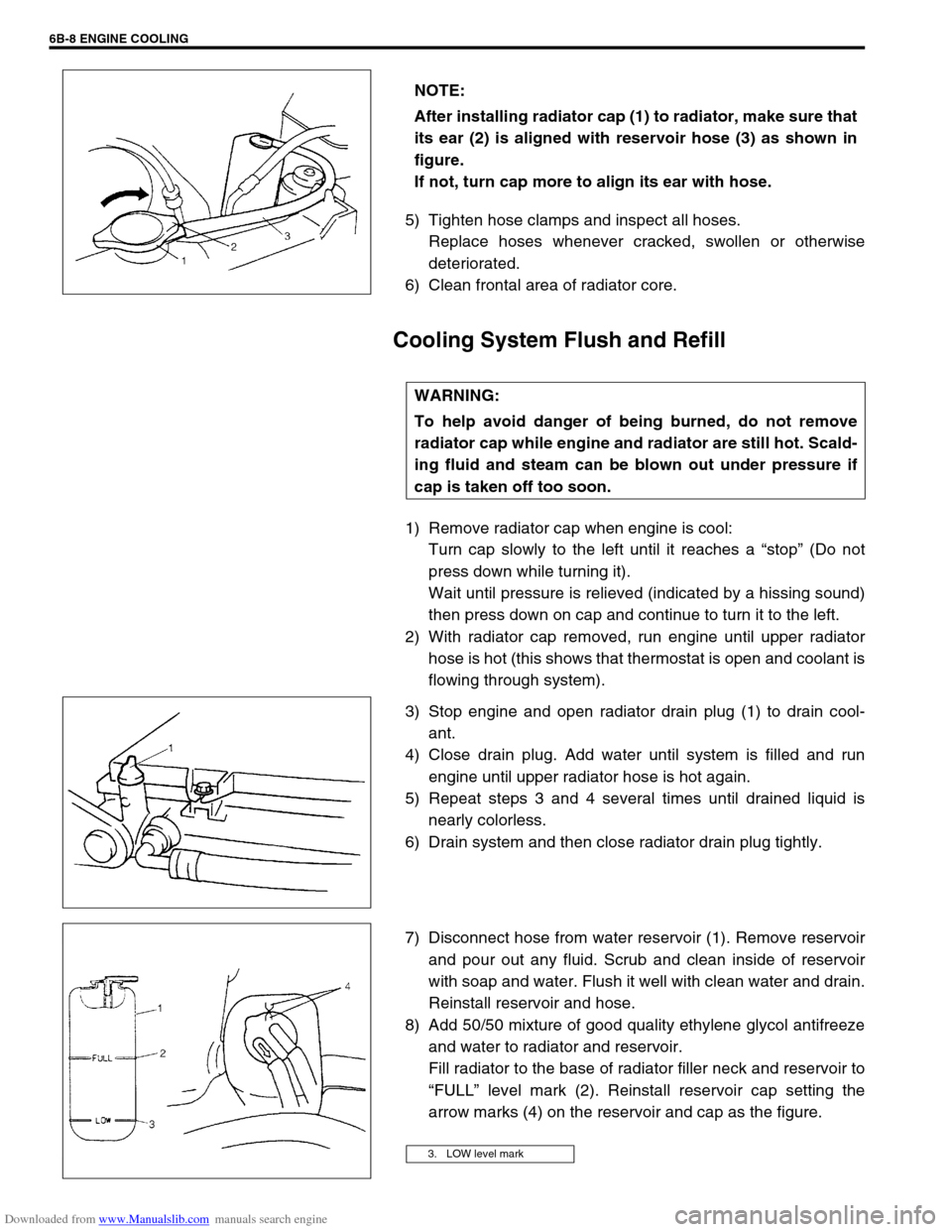
3) Stop engine and open radiator drain plug (1) to drain cool-
ant.
4) Close drain plug. Add water until system is filled and run
engine until upper radiator hose is hot again.
5) Repeat steps 3 and 4 several times until drained liquid is
nearly colorless.
6) Drain system and then close radiator drain plug tightly.
7) Disconnect hose from water reservoir (1). Remove reservoir
and pour out any fluid. Scrub and clean inside of reservoir
with soap and water. Flush it well with clean water and drain.
Reinstall reservoir and hose.
8) Add 50/50 mixture of good quality ethylene glycol antifreeze
and water to radiator and reservoir.
Fill radiator to the base of radiator filler neck and reservoir to
“FULL” level mark (2). Reinstall reservoir cap setting the
arrow marks (4) on the reservoir and cap as the figure. NOTE:
After installing radiator cap (1) to radiator, make sure that
its ear (2) is aligned with reservoir hose (3) as shown in
figure.
If not, turn cap more to align its ear with hose.
WARNING:
To help avoid danger of being burned, do not remove
radiator cap while engine and radiator are still hot. Scald-
ing fluid and steam can be blown out under pressure if
cap is taken off too soon.
3. LOW level mark
Page 587 of 687

Downloaded from www.Manualslib.com manuals search engine 6B-10 ENGINE COOLING
On-Vehicle Service
Cooling System Component
CAUTION:
Check to make sure that engine coolant temperature is cold before removing any part of cooling
system.
Disconnect negative cable at battery before removing any part.
1. Radiator 6. Thermostat 11. Water outlet cap
2. Reservoir 7. Thermostat cap 12. Thermostat case outlet pipe
3. Cooling fan shroud 8. Radiator outlet pipe 13. Thermostat cap bolt
4. Water outlet pipe 9. Heater pipe 14. Thermostat case bolt
5. Thermostat case 10. ECT sensor Tightening Torque
814 25 N·m (2.5 kg-m) 10 15 N·m (1.5 kg-m)
12 5
6
7
13 11 N·m
(1.1 kg-m) 119421
3