2005 SUZUKI JIMNY cooling
[x] Cancel search: coolingPage 4 of 687

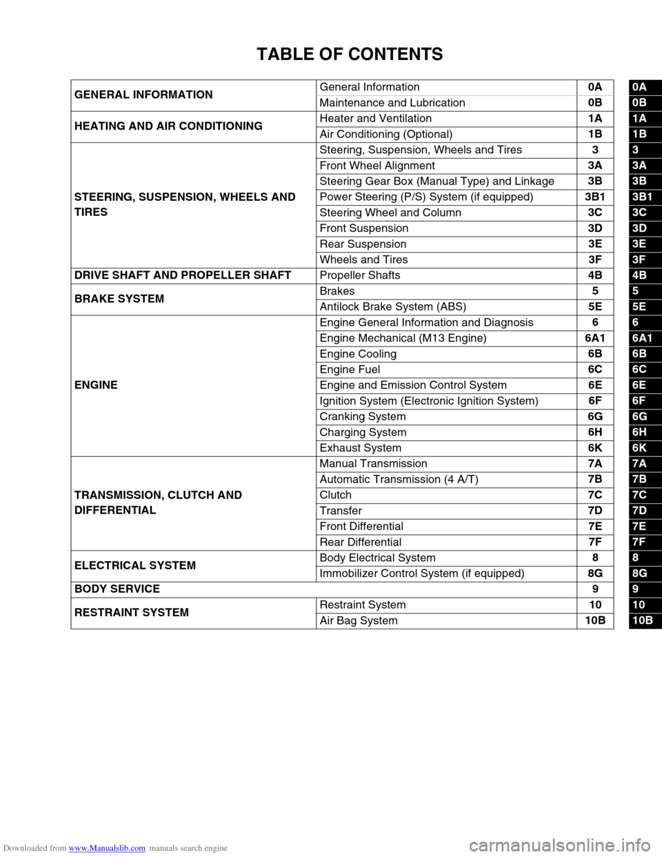
Downloaded from www.Manualslib.com manuals search engine TABLE OF CONTENTS
GENERAL INFORMATIONGeneral Information0A0A
Maintenance and Lubrication0B
0B
HEATING AND AIR CONDITIONINGHeater and Ventilation1A
1A
Air Conditioning (Optional)1B
1B
STEERING, SUSPENSION, WHEELS AND
TIRESSteering, Suspension, Wheels and Tires3
3
Front Wheel Alignment3A
3A
Steering Gear Box (Manual Type) and Linkage3B
3B
Power Steering (P/S) System (if equipped)3B1
3B1
Steering Wheel and Column3C
3C
Front Suspension3D
3D
Rear Suspension3E
3E
Wheels and Tires3F
3F
DRIVE SHAFT AND PROPELLER SHAFT
Propeller Shafts4B
4B
BRAKE SYSTEMBrakes5
5
Antilock Brake System (ABS)5E
5E
ENGINEEngine General Information and Diagnosis6
6
Engine Mechanical (M13 Engine)6A1
6A1
Engine Cooling6B
6B
Engine Fuel6C
6C
Engine and Emission Control System6E
6E
Ignition System (Electronic Ignition System)6F
6F
Cranking System6G
6G
Charging System6H
6H
Exhaust System6K
6K
TRANSMISSION, CLUTCH AND
DIFFERENTIALManual Transmission7A
7A
Automatic Transmission (4 A/T)7B
7B
Clutch7C
7C
Transfer7D
7D
Front Differential7E
7E
Rear Differential7F
7F
ELECTRICAL SYSTEMBody Electrical System8
8
Immobilizer Control System (if equipped)8G
8G
BODY SERVICE9
9
RESTRAINT SYSTEMRestraint System10
10
Air Bag System10B
10B
Page 23 of 687

Downloaded from www.Manualslib.com manuals search engine 0A-18 GENERAL INFORMATION
Warning, Caution and Information Labels
The figure below shows main labels among others that are attached to vehicle component parts.
When servicing and handling parts, refer to WARNING / CAUTION instructions printed on labels.
If any WARNING / CAUTION label is found stained or damaged, clean or replace it as necessary.
NOTE:
Air bag CAUTION / WARNING labels are attached on the vehicle equipped with air bag system only.
1. Emission control label (Australia only) 3. Air bag label on sun visor 5. Engine cooling fan label
2. Air bag label on engine hood 4. Radiator cap label
1. Air bag warning label on driver air bag (inflator) module 4. Air bag label on SDM
2. Air bag warning label on contact coil and combination switch assembly 5. Air bag label on passenger air bag (inflator) module
3. Air bag warning label on steering column 6. Seat belt pretensioner label on retractor
Page 36 of 687

Downloaded from www.Manualslib.com manuals search engine MAINTENANCE AND LUBRICATION 0B-5
Maintenance Service
Engine
Drive Belt
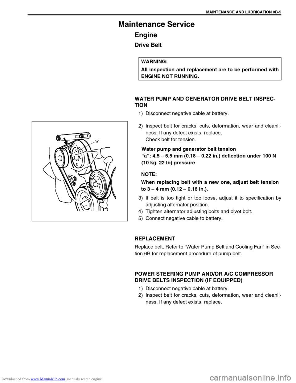
WATER PUMP AND GENERATOR DRIVE BELT INSPEC-
TION
1) Disconnect negative cable at battery.
2) Inspect belt for cracks, cuts, deformation, wear and cleanli-
ness. If any defect exists, replace.
Check belt for tension.
Water pump and generator belt tension
“a”: 4.5 – 5.5 mm (0.18 – 0.22 in.) deflection under 100 N
(10 kg, 22 lb) pressure
3) If belt is too tight or too loose, adjust it to specification by
adjusting alternator position.
4) Tighten alternator adjusting bolts and pivot bolt.
5) Connect negative cable to battery.
REPLACEMENT
Replace belt. Refer to “Water Pump Belt and Cooling Fan” in Sec-
tion 6B for replacement procedure of pump belt.
POWER STEERING PUMP AND/OR A/C COMPRESSOR
DRIVE BELTS INSPECTION (IF EQUIPPED)
1) Disconnect negative cable at battery.
2) Inspect belt for cracks, cuts, deformation, wear and cleanli-
ness. If any defect exists, replace. WARNING:
All inspection and replacement are to be performed with
ENGINE NOT RUNNING.
NOTE:
When replacing belt with a new one, adjust belt tension
to 3 – 4 mm (0.12 – 0.16 in.).
Page 39 of 687

Downloaded from www.Manualslib.com manuals search engine 0B-8 MAINTENANCE AND LUBRICATION
6) Replenish oil until oil level is brought to FULL level mark on
dipstick. (oil pan and oil filter capacity). The filler inlet is at
the top of the cylinder head cover.
It is recommended to use engine oil of SE, SF, SG, SH, SJ or
SL grade.
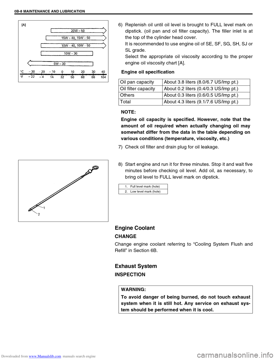
Select the appropriate oil viscosity according to the proper
engine oil viscosity chart [A].
Engine oil specification
7) Check oil filter and drain plug for oil leakage.
8) Start engine and run it for three minutes. Stop it and wait five
minutes before checking oil level. Add oil, as necessary, to
bring oil level to FULL level mark on dipstick.
Engine Coolant
CHANGE
Change engine coolant referring to “Cooling System Flush and
Refill” in Section 6B.
Exhaust System
INSPECTION
Oil pan capacity About 3.8 liters (8.0/6.7 US/lmp pt.)
Oil filter capacity About 0.2 liters (0.4/0.3 US/lmp pt.)
Others About 0.3 liters (0.6/0.5 US/lmp pt.)
Total About 4.3 liters (9.1/7.6 US/lmp pt.)
NOTE:
Engine oil capacity is specified. However, note that the
amount of oil required when actually changing oil may
somewhat differ from the data in the table depending on
various conditions (temperature, viscosity, etc.)
1. Full level mark (hole)
2. Low level mark (hole)
WARNING:
To avoid danger of being burned, do not touch exhaust
system when it is still hot. Any service on exhaust sys-
tem should be performed when it is cool.
Page 55 of 687

Downloaded from www.Manualslib.com manuals search engine 1A-2 HEATER AND VENTILATION
General Description
The heater, an in and out air selectable-type hot water heater, is so constructed that it is possible to assure an
agreeable ventilation at all times by providing the ventilator air outlets at the center and both sides (right and left)
of the instrument panel, the hot air outlet at a place close to the feet of front passengers, and the defroster air
outlets at places, right and left, along the windshield glass.
The heater and ventilation consist of following parts.
1. Side ventilator outlet 6. Ventilator duct 11. Heater core
2. Side defroster outlet 7. Control lever 12. Damper
3. Center ventilator outlet 8. Blower motor 13. Air inlet box (without air conditioning, without
other parts marked *)/cooling unit (if equipped
with air conditioning) 4. Heater unit 9. Blower resistor
5. Defroster duct 10. Blower fan switch/Blower fan and A/C
switch (if equipped with air conditioning)
Page 63 of 687

Downloaded from www.Manualslib.com manuals search engine 1B-2 AIR CONDITIONING (OPTIONAL)
Evacuating ................................................. 1B-23
Evacuating procedure ............................ 1B-23
Charging .................................................... 1B-25
Charging procedure ............................... 1B-25
Removing Manifold Gauge Set .................. 1B-28
Leak Test ................................................... 1B-28
On-Vehicle Service ...................................... 1B-29
Service Precaution ..................................... 1B-29
Refrigerant line ....................................... 1B-29
Handling refrigerant HFC-134a
(R-134a) ................................................. 1B-30
Condenser Assembly ................................. 1B-31
Receiver / Dryer ......................................... 1B-32
Condenser Cooling Fan Assembly ............ 1B-33Cooling Unit (Evaporator) .......................... 1B-34
A/C Evaporator Thermistor (A/C Evaporator
Temperature Sensor)................................. 1B-37
Expansion Valve ........................................ 1B-37
Dual Pressure Switch ................................ 1B-38
A/C Switch ................................................. 1B-39
Condenser Cooling Fan Motor Relay ........ 1B-39
Compressor ............................................... 1B-39
Magnet Clutch............................................ 1B-41
Lip Type Seal ............................................. 1B-45
Tightening Torque Specification................ 1B-46
Required Service Materials ......................... 1B-47
Special Tools ............................................... 1B-47
Page 64 of 687

Downloaded from www.Manualslib.com manuals search engine AIR CONDITIONING (OPTIONAL) 1B-3
General Description
Major Components and Location
1. Cooling unit 6. Suction hose 11. Foot air 16. Heater unit
2. Compressor 7. Receiver / dryer outlet pipe 12. Defroster air 17. A/C evaporator
3. Condenser assembly 8. Condenser outlet pipe 13. Demister air 18. Dual pressure switch
4. Receiver / dryer 9. Expansion valve 14. Fresh air 19. Low pressure service (charge) valve
5. Discharge hose 10. Ventilation air 15. Recirculation air 20. High pressure service (charge) valve
Page 66 of 687

Downloaded from www.Manualslib.com manuals search engine AIR CONDITIONING (OPTIONAL) 1B-5
Diagnosis
General Diagnosis Table
Condition Possible Cause Correction
Cool air won’t come
out (A/C system won’t
operative)No refrigerant Perform recover, evacuation and charging.
Fuse blown Check fuses in main and circuit fuse
boxes, and check short circuit to ground.
A/C switch faulty Check A/C switch.
Blower fan switch faulty Check blower fan switch referring to Sec-
tion 1A.
A/C evaporator thermistor faulty Check A/C evaporator thermistor.
Dual pressure switch faulty Check dual pressure switch.
Wiring or grounding faulty Repair as necessary.
ECT sensor faulty Check ECT sensor referring to Section 6E.
ECM and its circuit faulty Check ECM and its circuit referring to Sec-
tion 6E.
4WD controller faulty Check 4WD controller referring to Section
3D.
Cool air won’t come
out (A/C compressor
won't operative)ECM faulty Check ECM and its circuit referring to Sec-
tion 6E.
Magnet clutch faulty Check magnet clutch.
Compressor drive belt loosen or broken Adjust or replace drive belt.
Compressor faulty Check compressor.
Cool air won’t come
out (A/C condenser
cooling fan motor
won’t operative)Fuse blown Check “A/C” fuse in main fuse box, and
check short circuit to ground.
Wiring or grounding faulty Repair as necessary.
Condenser cooling fan motor relay
faultyCheck condenser cooling fan motor relay.
Condenser cooling fan motor faulty Check condenser cooling fan motor.
Cool air won’t come
out (Blower fan motor
won’t operative)Fuse blown Check fuses in main and circuit fuse
boxes, and check short circuit to ground.
Blower fan motor resistor faulty Check blower fan motor resistor referring
to Section 1A.
Blower fan switch faulty Check blower fan switch referring to Sec-
tion 1A.
Wiring or grounding faulty Repair as necessary.
Blower fan motor faulty Check blower fan motor referring to Sec-
tion 1A.