2005 SUZUKI JIMNY cooling
[x] Cancel search: coolingPage 246 of 687

Downloaded from www.Manualslib.com manuals search engine WHEELS AND TIRES 3F-3
Replacement Wheels
Wheels must be replaced if they are bent, dented, have excessive
lateral or radial runout, leak air through welds, have elongated
bolt holes, if lug nuts won’t stay tight, or if they are heavily rusted.
Wheels with greater runout than shown in “How to Measure
Wheel Runout” may cause objectional vibrations.
Wheels for replacement must be equivalent to the originally
equipped wheels in load capacity, diameter, rim width, off-set and
mounting configuration. A wheel of improper size or type may
affect wheel and bearing life, brake cooling, speedometer / odom-
eter calibration, ground clearance to the body and chassis.
How To Measure Wheel Runout
To measure the wheel runout, it is necessary to use accurate dial
indicator. The tire may be on or off the wheel. The wheel should
be installed to the wheel balancer of the like for proper measure-
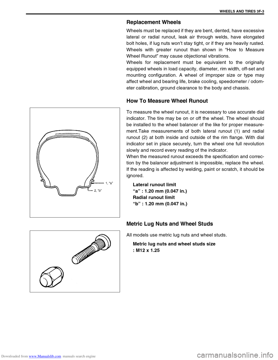
ment.Take measurements of both lateral runout (1) and radial
runout (2) at both inside and outside of the rim flange. With dial
indicator set in place securely, turn the wheel one full revolution
slowly and record every reading of the indicator.
When the measured runout exceeds the specification and correc-
tion by the balancer adjustment is impossible, replace the wheel.
If the reading is affected by welding, paint or scratch, it should be
ignored.
Lateral runout limit
“a” : 1.20 mm (0.047 in.)
Radial runout limit
“b” : 1.20 mm (0.047 in.)
Metric Lug Nuts and Wheel Studs
All models use metric lug nuts and wheel studs.
Metric lug nuts and wheel studs size
: M12 x 1.25
Page 358 of 687

Downloaded from www.Manualslib.com manuals search engine ENGINE GENERAL INFORMATION AND DIAGNOSIS 6-1
6F2
6G
6H
6K
7A
7A1
7B1
7C1
7D
7E
7F
8B
6
8D
8E
8B
9
10A
10B
SECTION 6
ENGINE GENERAL INFORMATION AND
DIAGNOSIS
GENERAL INFORMATION AND ENGINE DIAGNOSIS ..............................................................................
6-1
ENGINE MECHANICAL ...........................................................................................................................
6A1-1
ENGINE COOLING.....................................................................................................................................
6B-1
ENGINE FUEL ............................................................................................................................................
6C-1
ENGINE AND EMISSION CONTROL SYSTEM ........................................................................................
6E-1
IGNITION SYSTEM ....................................................................................................................................
6F-1
CRANKING SYSTEM .................................................................................................................................
6G-1
CHARGING SYSTEM .................................................................................................................................
6H-1
EXHAUST SYSTEM ...................................................................................................................................
6K-1
CONTENTS
General Information .......................................... 6-3
Statement on Cleanliness and Care ............... 6-3
General Information on Engine Service .......... 6-3
Precaution on fuel system service............... 6-4
Fuel pressure relief procedure .................... 6-5
Fuel leakage check procedure .................... 6-5
Engine Diagnosis .............................................. 6-6
General Description ........................................ 6-6
On-Board Diagnostic System (Vehicle with
Immobilizer Indicator Lamp) ............................ 6-6On-Board Diagnostic System (Vehicle without
Immobilizer Indicator Lamp)............................ 6-9
Precaution in Diagnosing Trouble ................. 6-10
Engine Diagnostic Flow Table ...................... 6-11
Customer problem inspection form
(example) .................................................. 6-13
Malfunction indicator lamp (MIL) check..... 6-14
Diagnostic trouble code (DTC) check ....... 6-14
Diagnostic trouble code (DTC)
clearance................................................... 6-15 WARNING:
For vehicles equipped with Supplemental Restraint (Air Bag) System :
Service on and around the air bag system components or wiring must be performed only by an
authorized SUZUKI dealer. Refer to “Air Bag System Components and Wiring Location View” under
“General Description” in air bag system section in order to confirm whether you are performing ser-
vice on or near the air bag system components or wiring. Please observe all WARNINGS and “Ser-
vice Precautions” under “On-Vehicle Service” in air bag system section before performing service
on or around the air bag system components or wiring. Failure to follow WARNINGS could result in
unintentional activation of the system or could render the system inoperative. Either of these two
conditions may result in severe injury.
Technical service work must be started at least 90 seconds after the ignition switch is turned to the
“LOCK” position and the negative cable is disconnected from the battery. Otherwise, the system
may be activated by reserve energy in the Sensing and Diagnostic Module (SDM).
NOTE:
Whether the following systems (parts) are used in the particular vehicle or not depends on vehicle
specifications. Be sure to bear this in mind when performing service work.
EGR valve
Heated oxygen sensor(s) or CO adjusting resistor
Three-way catalytic converter (TWC) and warm up three-way catalytic converter (WU-TWC)
Page 363 of 687

Downloaded from www.Manualslib.com manuals search engine 6-6 ENGINE GENERAL INFORMATION AND DIAGNOSIS
Engine Diagnosis
General Description
This vehicle is equipped with an engine and emission control system which are under control of ECM.
The engine and emission control system in this vehicle are controlled by ECM. ECM has an On-Board Diagnos-
tic system which detects a malfunction in this system and abnormality of those parts that influence the engine
exhaust emission. When diagnosing engine troubles, be sure to have full understanding of the outline of “On-
Board Diagnostic System” and each item in “Precaution in Diagnosing Trouble” and execute diagnosis accord-
ing to “ENGINE DIAGNOSTIC FLOW TABLE”.
There is a close relationship between the engine mechanical, engine cooling system, ignition system, exhaust
system, etc. and the engine and emission control system in their structure and operation. In case of an engine
trouble, even when the malfunction indicator lamp (MIL) doesn’t turn ON, it should be diagnosed according to
this flow table.
On-Board Diagnostic System (Vehicle with
Immobilizer Indicator Lamp)
ECM in this vehicle has following functions.
When the ignition switch is turned ON with the engine at a
stop, malfunction indicator lamp (MIL) (1) turns ON to check
the bulb of the malfunction indicator lamp (1).
When ECM detects a malfunction which gives an adverse
effect to vehicle emission while the engine is running, it
makes the malfunction indicator lamp (1) in the meter cluster
of the instrument panel turn ON or flash (flashing only when
detecting a misfire which can cause damage to the catalyst)
and stores the malfunction area in its memory.
(If it detects that continuously 3 driving cycles are normal
after detecting a malfunction, however, it makes MIL (1) turn
OFF although DTC stored in its memory will remain.)
As a condition for detecting a malfunction in some areas in
the system being monitored by ECM and turning ON the
malfunction indicator lamp (1) due to that malfunction, 2 driv-
ing cycle detection logic is adopted to prevent erroneous
detection.
When a malfunction is detected, engine and driving condi-
tions then are stored in ECM memory as freeze frame data.
(For the details, refer to description on Freeze frame data.)
It is possible to communicate by using not only SUZUKI scan
tool (2) but also generic scan tool. (Diagnostic information
can be accessed by using a scan tool.)
WARM-UP CYCLE
A warm-up cycle means sufficient vehicle operation such that the
coolant temperature has risen by at least 22 °C (40 °F) from
engine starting and reaches a minimum temperature of 70 °C
(160 °F).
Page 478 of 687

Downloaded from www.Manualslib.com manuals search engine ENGINE GENERAL INFORMATION AND DIAGNOSIS 6-121
TAble B-7 A/C Condenser Fan Control System Check
INSPECTION
Step Action Yes No
1 Check Fan Control System.
1) Connect scan tool to DLC with ignition switch OFF. See
Fig. 1.
2) Start engine and select “DATA LIST” mode on scan tool.
3) Warm up engine until coolant temp. is 110 °C, 230 °F or
higher and A/C switch turn OFF. (If engine coolant temp.
does not rise, check engine cooling system or ECT sen-
sor.)
Is A/C condenser fan started when engine coolant temp.
reached above temp.?A/C condenser fan con-
trol system is in good
condition.Go to Step 2.
2 Check A/C Condenser Fan Relay and Its Circuit.
1) Check DTC and pending DTC with scan tool.
Is DTC P0481 displayed?Go to DTC P0481 Diag.
Flow Table.Go to Step 3.
3 Check A/C Condenser Fan Relay (1).
1) Turn ignition switch OFF and remove A/C condenser fan
relay.
2) Check for proper connection to relay at terminals “A”
and “B”.
3) If OK, check that there is continuity between “A” and “B”
when battery is connected to terminals “C” and “D”. See
Fig. 2.
Is check result satisfactory?Go to Step 4. Replace A/C
condenser fan
relay.
Page 501 of 687

Downloaded from www.Manualslib.com manuals search engine 6A1-20 ENGINE MECHANICAL (M13 ENGINE)
13) Remove intake manifold (1) with throttle body (2) and EGR
pipe (3) from cylinder head (4), and then its gasket.
INSTALLATION
Reverse removal procedure for installation noting the followings.
Use new intake manifold gasket and EGR pipe gasket.
Tighten long bolt (1), short bolt (3) and nuts (2) to specified
torque.
Tightening torque
Intake manifold bolts and nuts
(a) : 25 N·m (2.5 kg-m, 18.0 lb-ft)
Check to ensure that all removed parts are back in place.
Reinstall any necessary parts which have not been rein-
stalled.
Adjust accelerator cable play referring to “Accelerator Cable
Adjustment” in Section 6E.
Refill cooling system referring to “Cooling System Flush and
Refill” in Section 6B.
Upon completion of installation, turn ignition switch ON but
engine OFF and check for fuel leaks.
Finally, start engine and check for engine coolant leaks.
Page 510 of 687

Downloaded from www.Manualslib.com manuals search engine ENGINE MECHANICAL (M13 ENGINE) 6A1-29
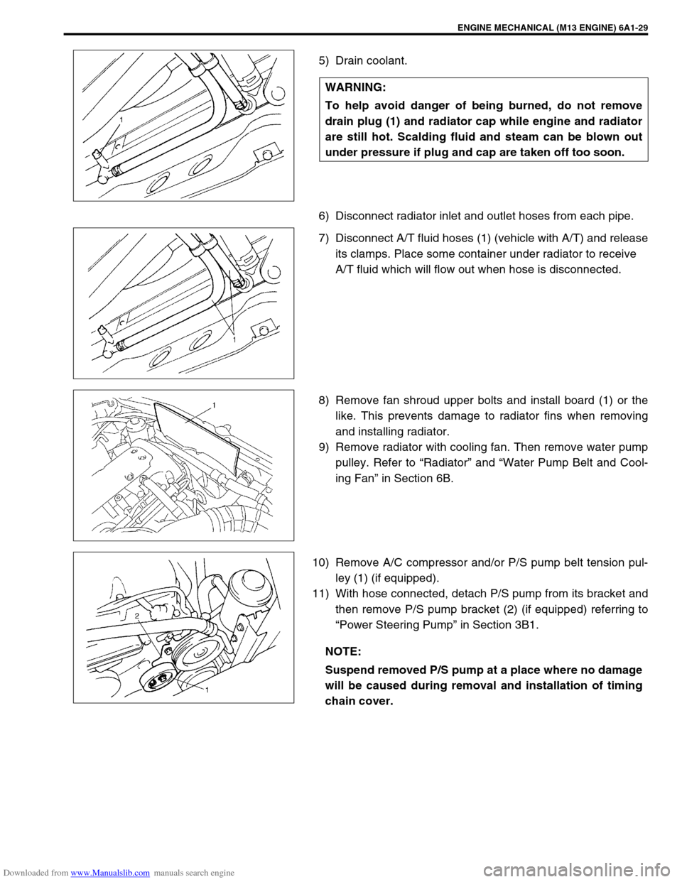
5) Drain coolant.
6) Disconnect radiator inlet and outlet hoses from each pipe.
7) Disconnect A/T fluid hoses (1) (vehicle with A/T) and release
its clamps. Place some container under radiator to receive
A/T fluid which will flow out when hose is disconnected.
8) Remove fan shroud upper bolts and install board (1) or the
like. This prevents damage to radiator fins when removing
and installing radiator.
9) Remove radiator with cooling fan. Then remove water pump
pulley. Refer to “Radiator” and “Water Pump Belt and Cool-
ing Fan” in Section 6B.
10) Remove A/C compressor and/or P/S pump belt tension pul-
ley (1) (if equipped).
11) With hose connected, detach P/S pump from its bracket and
then remove P/S pump bracket (2) (if equipped) referring to
“Power Steering Pump” in Section 3B1. WARNING:
To help avoid danger of being burned, do not remove
drain plug (1) and radiator cap while engine and radiator
are still hot. Scalding fluid and steam can be blown out
under pressure if plug and cap are taken off too soon.
NOTE:
Suspend removed P/S pump at a place where no damage
will be caused during removal and installation of timing
chain cover.
Page 513 of 687

Downloaded from www.Manualslib.com manuals search engine 6A1-32 ENGINE MECHANICAL (M13 ENGINE)
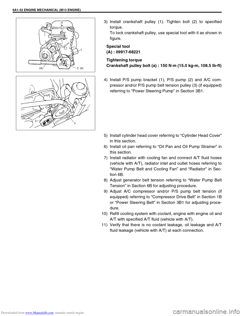
3) Install crankshaft pulley (1). Tighten bolt (2) to specified
torque.
To lock crankshaft pulley, use special tool with it as shown in
figure.
Special tool
(A) : 09917-68221
Tightening torque
Crankshaft pulley bolt (a) : 150 N·m (15.0 kg-m, 108.5 lb-ft)
4) Install P/S pump bracket (1), P/S pump (2) and A/C com-
pressor and/or P/S pump belt tension pulley (3) (if equipped)
referring to “Power Steering Pump” in Section 3B1.
5) Install cylinder head cover referring to “Cylinder Head Cover”
in this section.
6) Install oil pan referring to “Oil Pan and Oil Pump Strainer” in
this section.
7) Install radiator with cooling fan and connect A/T fluid hoses
(vehicle with A/T), radiator inlet and outlet hoses referring to
“Water Pump Belt and Cooling Fan” and “Radiator” in Sec-
tion 6B.
8) Adjust generator belt tension referring to “Water Pump Belt
Tension” in Section 6B for adjusting procedure.
9) Adjust A/C compressor and/or P/S pump belt tension (if
equipped) referring to “Compressor Drive Belt” in Section 1B
or “Power Steering Belt” in Section 3B1 for adjusting proce-
dure.
10) Refill cooling system with coolant, engine with engine oil and
A/T with specified A/T fluid (vehicle with A/T).
11) Verify that there is no coolant leakage, oil leakage and A/T
fluid leakage (vehicle with A/T) at each connection.
Page 528 of 687

Downloaded from www.Manualslib.com manuals search engine ENGINE MECHANICAL (M13 ENGINE) 6A1-47
5) After applying engine oil to housing bolts, tighten them tem-
porarily first. Then tighten them by the following numerical
order in figure. Tighten a little at a time and evenly among
bolts and repeat tightening sequence two or three times
before they are tightened to specified torque.
Tightening torque
Camshaft housing bolts (a) : 11 N·m (1.1 kg-m, 8.0 lb-ft)
6) Install timing chain with crankshaft sprocket referring to
“Timing Chain and Chain Tensioner” in this section.
7) Install timing chain cover referring to “Timing Chain Cover” in
this section.
8) Check valve lashes referring to “Valve Lash” in this section.
9) Install cylinder head cover and oil pan referring to “Cylinder
Head Cover” and “Oil Pan and Oil Pump Strainer” in this sec-
tion.
10) Install radiator with cooling fan and connect A/T fluid hoses
(vehicle with A/T), radiator inlet and outlet hoses referring to
“Water Pump Belt and Cooling Fan” and “Radiator” in Sec-
tion 6B.
11) Adjust generator belt tension referring to “Water Pump Belt
Tension” in Section 6B.
12) Adjust A/C compressor and/or P/S pump belt tension (if
equipped) referring to “Compressor Drive Belt” in Section 1B
or “Power Steering Belt” in Section 3B1.
13) Refill cooling system with coolant, engine with engine oil and
A/T with specified A/T fluid (vehicle with A/T).
14) Verify that there is no coolant leakage, oil leakage and A/T
fluid leakage (vehicle with A/T) at each connection.