Page 590 of 687

Downloaded from www.Manualslib.com manuals search engine ENGINE COOLING 6B-13
Water Pump Belt and Cooling Fan
REMOVAL
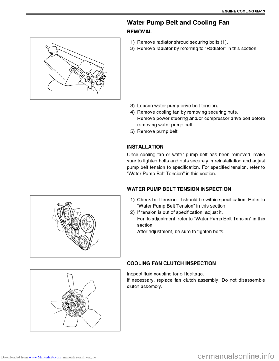
1) Remove radiator shroud securing bolts (1).
2) Remove radiator by referring to “Radiator” in this section.
3) Loosen water pump drive belt tension.
4) Remove cooling fan by removing securing nuts.
Remove power steering and/or compressor drive belt before
removing water pump belt.
5) Remove pump belt.
INSTALLATION
Once cooling fan or water pump belt has been removed, make
sure to tighten bolts and nuts securely in reinstallation and adjust
pump belt tension to specification. For specified tension, refer to
“Water Pump Belt Tension” in this section.
WATER PUMP BELT TENSION INSPECTION
1) Check belt tension. It should be within specification. Refer to
“Water Pump Belt Tension” in this section.
2) If tension is out of specification, adjust it.
For its adjustment, refer to “Water Pump Belt Tension” in this
section.
After adjustment, be sure to tighten bolts.
COOLING FAN CLUTCH INSPECTION
Inspect fluid coupling for oil leakage.
If necessary, replace fan clutch assembly. Do not disassemble
clutch assembly.
Page 591 of 687

Downloaded from www.Manualslib.com manuals search engine 6B-14 ENGINE COOLING
Radiator
REMOVAL
1) Drain cooling system.
2) Remove radiator shroud.
3) Disconnect water hoses from radiator.
4) With automatic transmission (A/T) vehicle, disconnect addi-
tional two fluid hoses from radiator.
Place some container under radiator to receive A/T fluid
which will flow out when hose is disconnected.
5) Install radiator protection board to between radiator and
cooling fan.
6) Remove radiator after removing two bolts (1).
INSPECTION
If the water side of the radiator is found excessively rusted or cov-
ered with scales, clean it by flushing with the radiator cleaner
compound.
This flushing should be carried out at regular intervals for scale or
rust formation advances with time even where a recommended
type of coolant is used. Periodical flushing will prove more eco-
nomical.
Inspect the radiator cores and straighten the flattened or bent
fins, if any. Clean the cores, removing road grimes and trashes.
Excessive rust or scale formation on the wet side of the radiator
lowers the cooling efficiency.
Flattened or bent fins obstruct the flow of air through the core to
impede heat dissipation.
Radiator flushing interval recommended
Two years
INSTALLATION
Reverse removal procedures.
NOTE:
Refill cooling system with proper coolant referring to
“Coolant” and “Cooling System Flush and Refill” in
this section.
With automatic transmission vehicle, fill A/T fluid up to
specified level. For procedure to check A/T fluid and its
level, refer to “Changing Fluid” in Section 7B.
After installation, check each joint for leakage.
Page 592 of 687
Downloaded from www.Manualslib.com manuals search engine ENGINE COOLING 6B-15
Water Pump
COMPONENTS
REMOVAL
1) Drain cooling system.
Refer to Step 6) of “Cooling System Flush and Refill” in this
section.
2) Remove the radiator shroud.
3) Remove radiator referring to “Radiator” in this section.
4) Loosen water pump drive belt tension.
Then remove water pump pulley (2) with fan clutch (3) and
pump drive belt.
5) Remove water pump assembly (1).
1. Water pump 4. Radiator cooling fan 7. Radiator cooling fan mounting bolt
2. Water pump pulley 5. Water pump mounting bolts Tightening Torque
3. Radiator cooling fan clutch 6. Water pump pulley and fan clutch mounting nuts
1. Drain plug
Page 593 of 687

Downloaded from www.Manualslib.com manuals search engine 6B-16 ENGINE COOLING
INSPECTION
Rotate water pump by hand to check for smooth operation.
If pump does not rotate smoothly or makes an abnormal
noise, replace it.
INSTALLATION
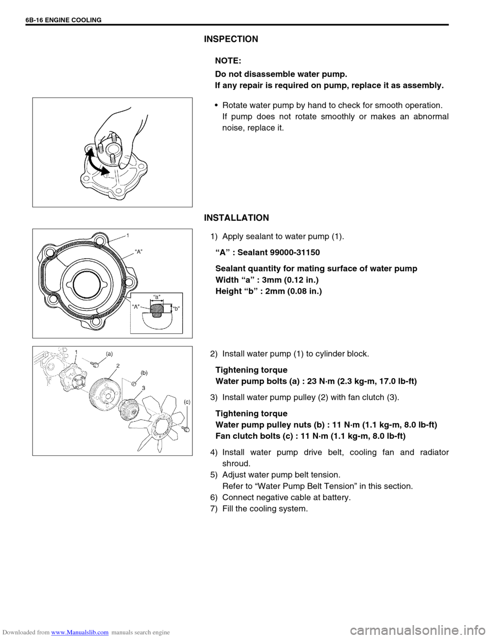
1) Apply sealant to water pump (1).
“A” : Sealant 99000-31150
Sealant quantity for mating surface of water pump
Width “a” : 3mm (0.12 in.)
Height “b” : 2mm (0.08 in.)
2) Install water pump (1) to cylinder block.
Tightening torque
Water pump bolts (a) : 23 N·m (2.3 kg-m, 17.0 lb-ft)
3) Install water pump pulley (2) with fan clutch (3).
Tightening torque
Water pump pulley nuts (b) : 11 N·m (1.1 kg-m, 8.0 lb-ft)
Fan clutch bolts (c) : 11 N·m (1.1 kg-m, 8.0 lb-ft)
4) Install water pump drive belt, cooling fan and radiator
shroud.
5) Adjust water pump belt tension.
Refer to “Water Pump Belt Tension” in this section.
6) Connect negative cable at battery.
7) Fill the cooling system.NOTE:
Do not disassemble water pump.
If any repair is required on pump, replace it as assembly.
Page 594 of 687
Downloaded from www.Manualslib.com manuals search engine ENGINE COOLING 6B-17
Required Service Material
Tightening Torque Specification
MaterialRecommended SUZUKI product
(Part Number)Use
Ethylene glycol base
coolant (Anti-freeze /
Anti-corrosion coolant)–Additive to engine cooling system for improving
cooling efficiency and for protection against
rusting.
SealantSUZUKI BOND NO.1207C
(99000 – 31150)To apply to water pump mating surface.
Fastening partTightening torque
Nm kg-m lb-ft
Water pump bolt 23 2.3 17.0
Thermostat cap bolt 11 1.1 8.0
Thermostat case bolt 25 2.5 18.0
Fun clutch bolt 11 1.1 8.0
Page 595 of 687
Downloaded from www.Manualslib.com manuals search engine 6B-18 ENGINE COOLING
Page 623 of 687
Downloaded from www.Manualslib.com manuals search engine 6E-18 ENGINE AND EMISSION CONTROL SYSTEM
Air Intake System
Throttle body
ON-VEHICLE INSPECTION
Check that throttle valve lever (1) moves smoothly.
REMOVAL
1) Disconnect negative cable at battery.
2) Drain cooling system.
3) Disconnect accelerator cable (1) from throttle valve lever.
1. Throttle body 4. Gasket 7. TP sensor screws
2. Throttle body gasket 5. Idle air control valve Tightening torque
3. TP sensor 6. IAC valve screws Do not reuse
Page 625 of 687
Downloaded from www.Manualslib.com manuals search engine 6E-20 ENGINE AND EMISSION CONTROL SYSTEM
INSTALLATION
1) Clean mating surfaces and install throttle body gasket to
intake manifold.
Use new gasket.
2) Connect engine coolant hoses.
3) Install throttle body (1) to intake manifold.
4) Connect connectors to TP sensor (2) and IAC valve (3)
securely.
5) Install air cleaner outlet No.2 hose (1) and pipe.
6) Connect accelerator cable and adjust cable play to specifica-
tion.
7) Refill cooling system.
8) Connect negative cable at battery.