2005 SUZUKI JIMNY gas type
[x] Cancel search: gas typePage 13 of 687
Downloaded from www.Manualslib.com manuals search engine 0A-8 GENERAL INFORMATION
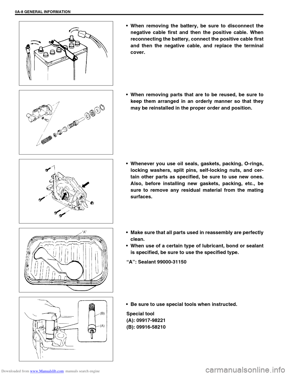
When removing the battery, be sure to disconnect the
negative cable first and then the positive cable. When
reconnecting the battery, connect the positive cable first
and then the negative cable, and replace the terminal
cover.
When removing parts that are to be reused, be sure to
keep them arranged in an orderly manner so that they
may be reinstalled in the proper order and position.
Whenever you use oil seals, gaskets, packing, O-rings,
locking washers, split pins, self-locking nuts, and cer-
tain other parts as specified, be sure to use new ones.
Also, before installing new gaskets, packing, etc., be
sure to remove any residual material from the mating
surfaces.
Make sure that all parts used in reassembly are perfectly
clean.
When use of a certain type of lubricant, bond or sealant
is specified, be sure to use the specified type.
“A”: Sealant 99000-31150
Be sure to use special tools when instructed.
Special tool
(A): 09917-98221
(B): 09916-58210
Page 224 of 687

Downloaded from www.Manualslib.com manuals search engine REAR SUSPENSION 3E-5
Check wheel bearings for wear. When measuring thrust
play, apply a dial gauge to axle shaft center after removing
wheel center cap from wheel disc.
When measurement exceeds limit, replace bearing.
Rear wheel bearing thrust play limit
: 0.8 mm (0.03 in.)
By rotating wheel actually, check wheel bearing for noise and
smooth rotation. If it is defective, replace bearing.
On-Vehicle Service
Rear Shock Absorber
The shock absorber is non-adjustable, non-refillable, and cannot be disassembled. The only service the shock
absorber requires is replacement when it has lost its resistance, is damaged, or leaking fluid.
REMOVAL
1) Hoist vehicle.
2) Support rear axle housing (1) by using floor jack (2) to pre-
vent it from lowering.
WARNING:
When discarding shock absorber, be sure to refer to instructions in “Rear Shock Absorber Check” in
this section for proper procedure as it is gas sealed type.
Page 361 of 687
Downloaded from www.Manualslib.com manuals search engine 6-4 ENGINE GENERAL INFORMATION AND DIAGNOSIS
Precaution on fuel system service
Work must be done with no smoking, in a well-ventilated
area and away from any open flames.
As fuel feed line (between fuel pump and fuel delivery pipe)
is still under high fuel pressure even after engine was
stopped, loosening or disconnecting fuel feed line directly
may cause dangerous spout of fuel to occur where loosened
or disconnected.
Before loosening or disconnecting fuel feed line, make sure
to release fuel pressure according to “FUEL PRESSURE
RELIEF PROCEDURE”. A small amount of fuel may be
released after the fuel line is disconnected. In order to
reduce the chance of personal injury, cover the fitting to be
disconnected with a shop cloth. Put that cloth in an approved
container when disconnection is completed.
Never run engine with fuel pump relay disconnected when
engine and exhaust system are hot.
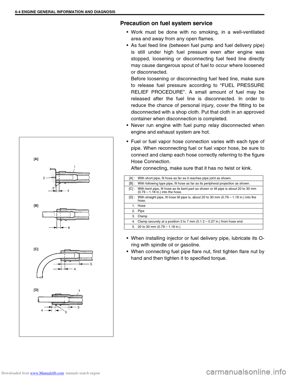
Fuel or fuel vapor hose connection varies with each type of
pipe. When reconnecting fuel or fuel vapor hose, be sure to
connect and clamp each hose correctly referring to the figure
Hose Connection.
After connecting, make sure that it has no twist or kink.
When installing injector or fuel delivery pipe, lubricate its O-
ring with spindle oil or gasoline.
When connecting fuel pipe flare nut, first tighten flare nut by
hand and then tighten it to specified torque.
[A] : With short pipe, fit hose as far as it reaches pipe joint as shown.
[B] : With following type pipe, fit hose as far as its peripheral projection as shown.
[C] : With bent pipe, fit hose as its bent part as shown or till pipe is about 20 to 30 mm
(0.79 – 1.18 in.) into the hose.
[D] : With straight pipe, fit hose till pipe is, about 20 to 30 mm (0.79 – 1.18 in.) into the
hose.
1. Hose
2. Pipe
3. Clamp
4. Clamp securely at a position 3 to 7 mm (0.1 2 – 0.27 in.) from hose end.
5. 20 to 30 mm (0.79 – 1.18 in.)
Page 421 of 687
Downloaded from www.Manualslib.com manuals search engine 6-64 ENGINE GENERAL INFORMATION AND DIAGNOSIS
DTC P0136 Heated Oxygen Sensor (HO2S) Circuit Malfunction (Sensor-2)
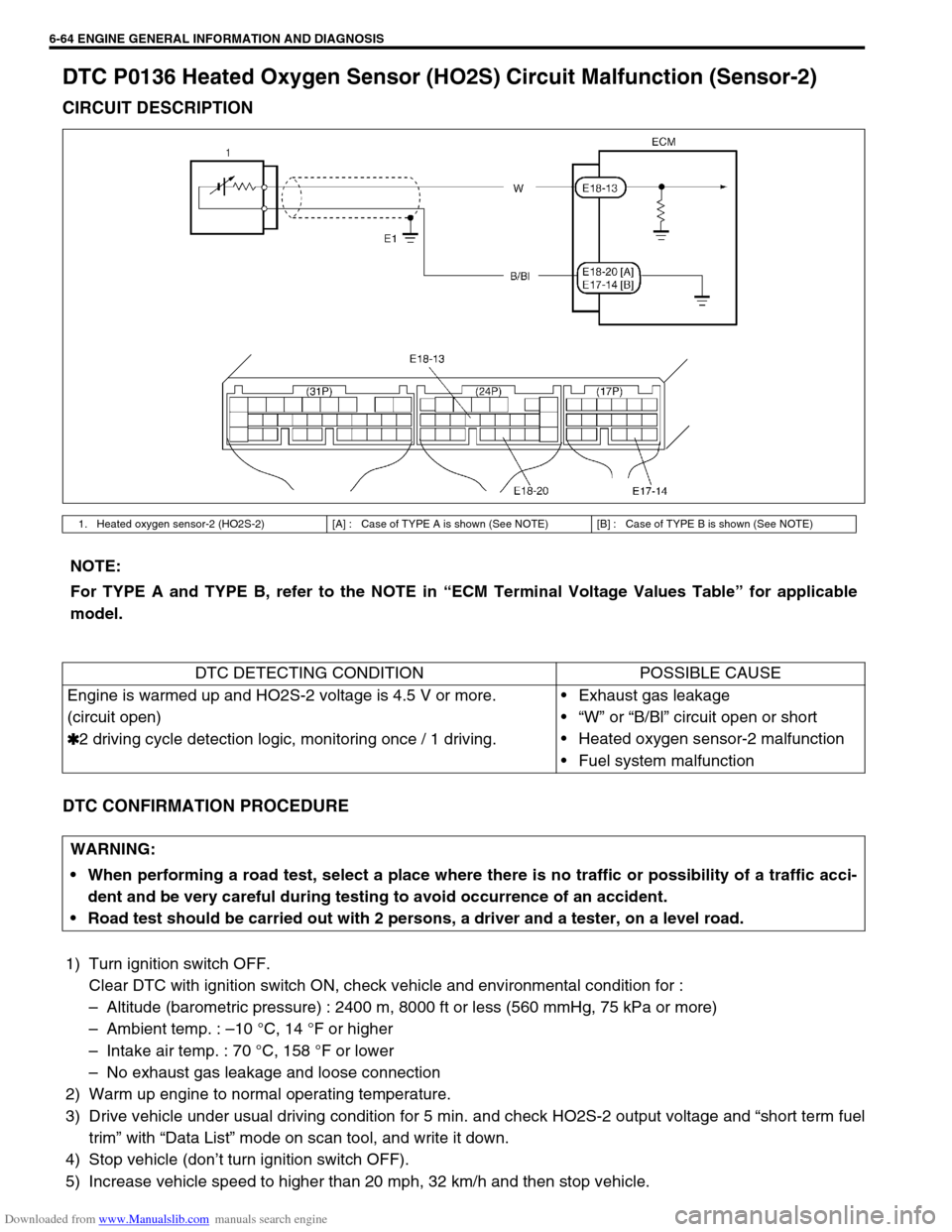
CIRCUIT DESCRIPTION
DTC CONFIRMATION PROCEDURE
1) Turn ignition switch OFF.
Clear DTC with ignition switch ON, check vehicle and environmental condition for :
–Altitude (barometric pressure) : 2400 m, 8000 ft or less (560 mmHg, 75 kPa or more)
–Ambient temp. : –10 °C, 14 °F or higher
–Intake air temp. : 70 °C, 158 °F or lower
–No exhaust gas leakage and loose connection
2) Warm up engine to normal operating temperature.
3) Drive vehicle under usual driving condition for 5 min. and check HO2S-2 output voltage and “short term fuel
trim” with “Data List” mode on scan tool, and write it down.
4) Stop vehicle (don’t turn ignition switch OFF).
5) Increase vehicle speed to higher than 20 mph, 32 km/h and then stop vehicle.
1. Heated oxygen sensor-2 (HO2S-2) [A] : Case of TYPE A is shown (See NOTE) [B] : Case of TYPE B is shown (See NOTE)
NOTE:
For TYPE A and TYPE B, refer to the NOTE in “ECM Terminal Voltage Values Table” for applicable
model.
DTC DETECTING CONDITION POSSIBLE CAUSE
Engine is warmed up and HO2S-2 voltage is 4.5 V or more.
(circuit open)
✱
✱✱ ✱2 driving cycle detection logic, monitoring once / 1 driving.Exhaust gas leakage
“W” or “B/Bl” circuit open or short
Heated oxygen sensor-2 malfunction
Fuel system malfunction
WARNING:
When performing a road test, select a place where there is no traffic or possibility of a traffic acci-
dent and be very careful during testing to avoid occurrence of an accident.
Road test should be carried out with 2 persons, a driver and a tester, on a level road.
Page 445 of 687

Downloaded from www.Manualslib.com manuals search engine 6-88 ENGINE GENERAL INFORMATION AND DIAGNOSIS
DTC P0420 Catalyst System Efficiency below Threshold
CIRCUIT DESCRIPTION
ECM monitors oxygen concentration in the exhaust gas which has passed the three way catalytic converter by
HO2S-2.
When the catalyst is functioning properly, the variation cycle of HO2S-2 output voltage (oxygen concentration) is
slower than that of HO2S-1 output voltage because of the amount of oxygen in the exhaust gas which has been
stored in the catalyst.
REFERENCE
1. Heated oxygen sensor-1 3. Three way catalytic converter 5. To the sensor [B] : Case of TYPE B is shown
(See NOTE)
2. Warm up three way catalytic
converter4. Heated oxygen sensor-2 [A] : Case of TYPE A is shown
(See NOTE)
NOTE:
For TYPE A and TYPE B, refer to the NOTE in “ECM Terminal Voltage Values Table” for applicable
model.
1. Engine running at closed loop
condition2. Fuel cut 3. Idle after fuel cut [A] : Oscilloscope waveforms
Page 483 of 687

Downloaded from www.Manualslib.com manuals search engine 6A1-2 ENGINE MECHANICAL (M13 ENGINE)
General Description
Engine
The engine is water-cooled, in line 4 cylinders, 4 stroke cycle gasoline unit with its DOHC (Double overhead
camshaft) valve mechanism arranged for “V” type valve configuration and 16 valves (4 valves / one cylinder).
The double overhead camshaft is mounted over the cylinder head; it is driven from crankshaft through timing
chain, and no push rods are provided in the valve train system.
Page 581 of 687
Downloaded from www.Manualslib.com manuals search engine 6B-4 ENGINE COOLING
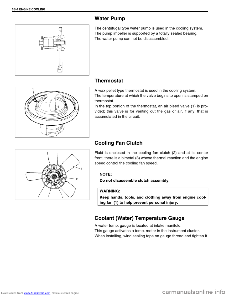
Water Pump
The centrifugal type water pump is used in the cooling system.
The pump impeller is supported by a totally sealed bearing.
The water pump can not be disassembled.
Thermostat
A wax pellet type thermostat is used in the cooling system.
The temperature at which the valve begins to open is stamped on
thermostat.
In the top portion of the thermostat, an air bleed valve (1) is pro-
vided; this valve is for venting out the gas or air, if any, that is
accumulated in the circuit.
Cooling Fan Clutch
Fluid is enclosed in the cooling fan clutch (2) and at its center
front, there is a bimetal (3) whose thermal reaction and the engine
speed control the cooling fan speed.
Coolant (Water) Temperature Gauge
A water temp. gauge is located at intake manifold.
This gauge activates a temp. meter in the instrument cluster.
When installing, wind sealing tape on gauge thread and tighten it.
NOTE:
Do not disassemble clutch assembly.
WARNING:
Keep hands, tools, and clothing away from engine cool-
ing fan (1) to help prevent personal injury.
Page 654 of 687
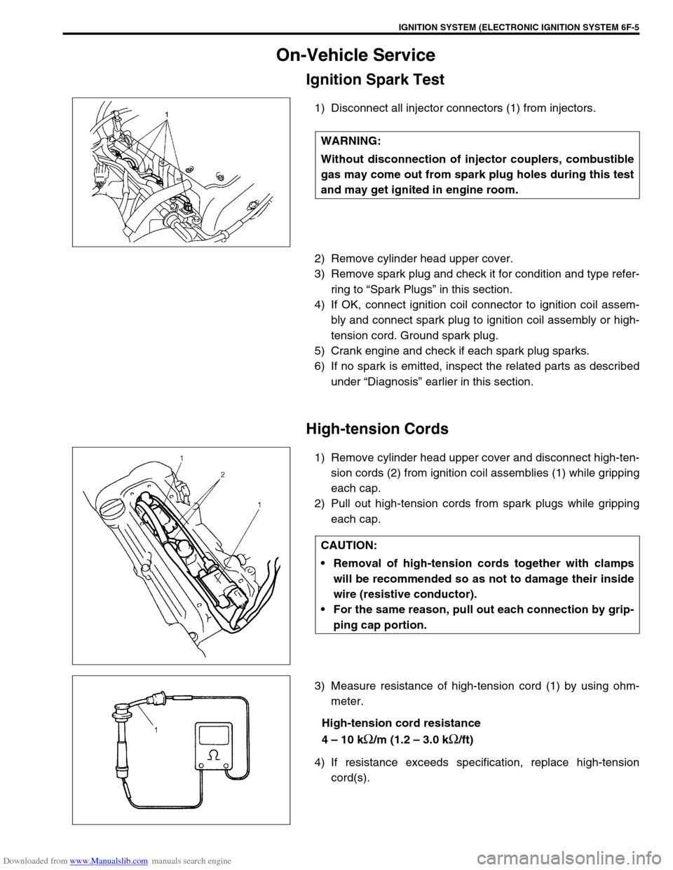
Downloaded from www.Manualslib.com manuals search engine IGNITION SYSTEM (ELECTRONIC IGNITION SYSTEM 6F-5
On-Vehicle Service
Ignition Spark Test
1) Disconnect all injector connectors (1) from injectors.
2) Remove cylinder head upper cover.
3) Remove spark plug and check it for condition and type refer-
ring to “Spark Plugs” in this section.
4) If OK, connect ignition coil connector to ignition coil assem-
bly and connect spark plug to ignition coil assembly or high-
tension cord. Ground spark plug.
5) Crank engine and check if each spark plug sparks.
6) If no spark is emitted, inspect the related parts as described
under “Diagnosis” earlier in this section.
High-tension Cords
1) Remove cylinder head upper cover and disconnect high-ten-
sion cords (2) from ignition coil assemblies (1) while gripping
each cap.
2) Pull out high-tension cords from spark plugs while gripping
each cap.
3) Measure resistance of high-tension cord (1) by using ohm-
meter.
High-tension cord resistance
4 – 10 k
Ω/m (1.2 – 3.0 kΩ/ft)
4) If resistance exceeds specification, replace high-tension
cord(s). WARNING:
Without disconnection of injector couplers, combustible
gas may come out from spark plug holes during this test
and may get ignited in engine room.
CAUTION:
Removal of high-tension cords together with clamps
will be recommended so as not to damage their inside
wire (resistive conductor).
For the same reason, pull out each connection by grip-
ping cap portion.