2005 SUZUKI JIMNY clutch pedal
[x] Cancel search: clutch pedalPage 26 of 687

Downloaded from www.Manualslib.com manuals search engine GENERAL INFORMATION 0A-21
Abbreviations May Be Used In This Manual
Abbreviations
AABC
ATDC
API
ATF
ALR
AC
A/T
A/C
ABDC
A/F
A-ELRAnti-lock Brake System
After Top Dead Center
American Petroleum Institute
Automatic Transmission Fluid
Automatic Locking Retractor
Alternating Current
Automatic Transmission
Air Conditioning
After Bottom Dead Center
Air Fuel Mixture Ratio
Automatic-Emergency
Locking RetractorEEBCM
ECM
ECT Sensor
EGR
EGRT Sensor
EFE Heater
ELR
EPS
EVAP
EVAP CanisterElectronic Brake Control Module,
ABS Control Module
Engine Control Module
Engine Coolant Temperature
Sensor (Water Temp. Sensor,
WTS)
Exhaust Gas Recirculation
EGR Temperature Sensor
(Recirculated Exhaust Gas Temp.
Sensor, REGTS)
Early Fuel Evaporation
Heater (Positive Temperature
Coefficient, PTC Heater)
Emergency Locking Retractor
Electronic Power Steering
Evaporative Emission
Evaporative Emission Canister
(Charcoal Canister) BB+
BTDC
BBDCBattery Positive Voltage
Before Top Dead Center
Before Bottom Dead Center
CCKT
CMP Sensor
CO
CPP Switch
CPU
CRSCircuit
Camshaft Position Sensor
(Crank Angle Sensor, CAS)
Carbon Monoxide
Clutch Pedal Position Switch
(Clutch Switch, Clutch Start
Switch)
Central Processing Unit
Child Restraint SystemF 4WD 4 Wheel Drive
GGEN
GNDGenerator
Ground
HHC
HO2SHydrocarbons
Heated Oxygen Sensor
DDC
DLC
DOHC
DOJ
DRL
DTCDirect Current
Data Link Connector
(Assembly Line Diag. Link, ALDL,
Serial Data Link, SDL)
Double Over Head Camshaft
Double Offset Joint
Daytime Running Light
Diagnostic Trouble Code
(Diagnostic Code)IIAC Valve
IAT Sensor
ICM
IG
ISC ActuatorIdle Air Control Valve (Idle Speed
Control Solenoid Valve, ISC
Solenoid Valve)
Intake Air Temperature Sensor
(Air temperature Sensor, ATS)
Immobilizer Control Module
Ignition
Idle Speed Control Actuator
(Motor)
Page 34 of 687

Downloaded from www.Manualslib.com manuals search engine MAINTENANCE AND LUBRICATION 0B-3
IntervalKm (x 1,000) 153045607590
Miles (x 1,000) 9 18 27 36 45 54
Months 12 24 36 48 60 72
CHASSIS AND BODY
Clutch (pedal height and travel)–I–I–I
Brake discs and pads (thickness, wear, damage) I I I I I I
Brake drums and shoes (wear, damage)–I–I–I
Brake hoses and pipes (leakage, damage, clamp)–I–I–I
Brake fluid–R–R–R
Brake lever and cable (damage, stroke, operation) Inspect at first 15,000 km (9,000 miles) only.
Tires (wear, damage, rotation) I I I I I I
Wheel discs (damage) I I I I I I
Suspension system (tightness, damage, rattle, breakage)–I–I–I
Propeller shafts––I––I
Manual transmission oil (leakage, level) (I: 1st 15,000 km only) I–R––R
Automatic transmission Fluid level–I–I–I
Fluid change Replace every 165,000 km (99,000 miles).
Fluid hose–––R––
Transfer oil (leakage, level) I–I–I–
Differential oil (leakage, level) (R: 1st 15,000 km only) R or I–I–I–
Steering system (tightness, damage, breakage, rattle)–I–I–I
Power steering (if equipped) I I I I I I
All latches, hinges and locks–I–I–I
NOTE:
“R”: Replace or change
“I”: Inspect and correct, replace or lubricate if necessary
Page 42 of 687

Downloaded from www.Manualslib.com manuals search engine MAINTENANCE AND LUBRICATION 0B-11
PCV (Positive Crankcase Ventilation) Valve
INSPECTION
Check crankcase ventilation hose and PCV hose for leaks, cracks
or clog, and PCV valve for stick or clog. Refer to “PCV System” of
Section 6E for PCV valve checking procedure.
Fuel Evaporative Emission Control System
INSPECTION
1) Visually inspect hoses for cracks, damage, or excessive
bends. Inspect all clamps for damage and proper position.
2) Check EVAP canister for operation and clog, referring to
“Evaporative Emission (EVAP) Control System” in Section
6E.
If a malfunction is found, repair or replace.
Chassis and Body
Clutch
INSPECTION
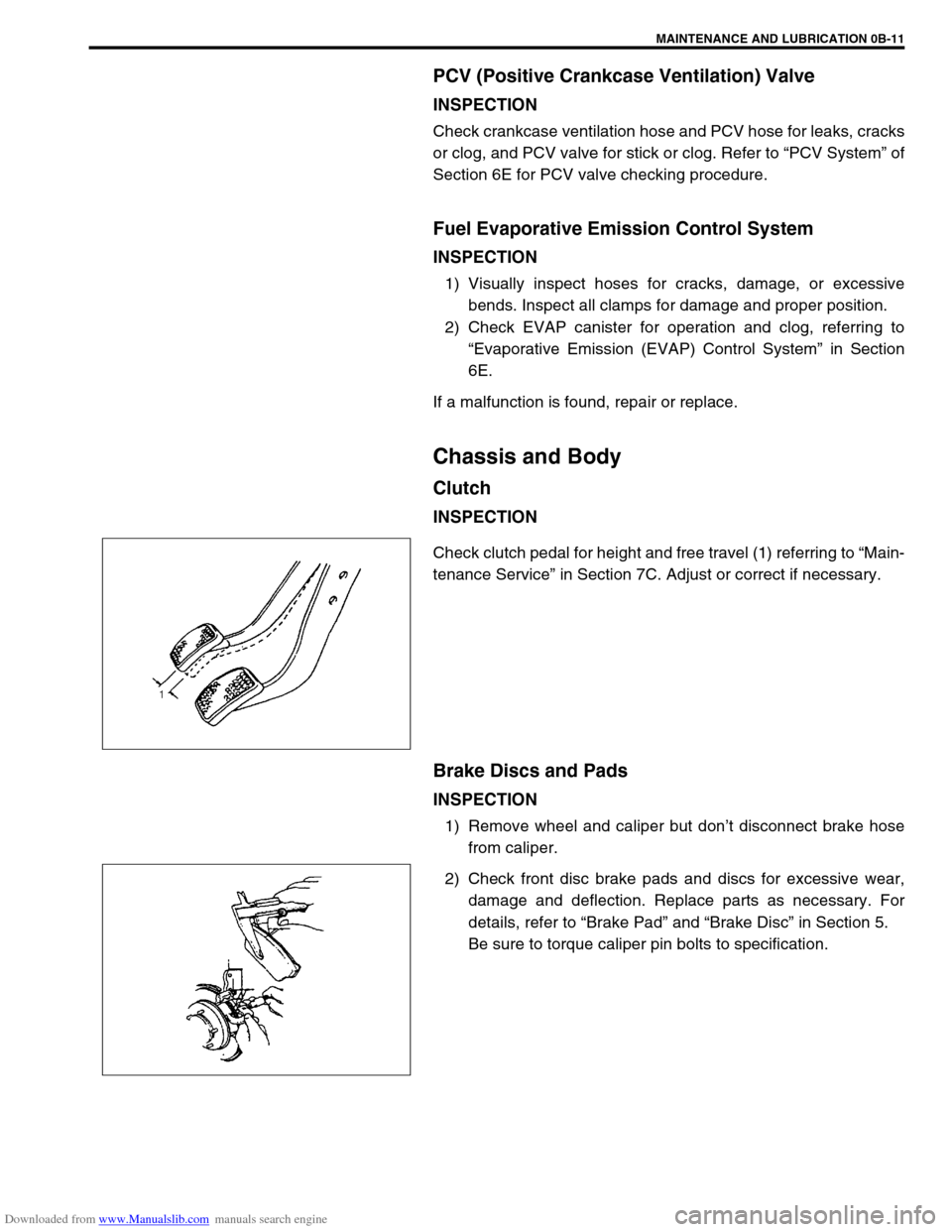
Check clutch pedal for height and free travel (1) referring to “Main-
tenance Service” in Section 7C. Adjust or correct if necessary.
Brake Discs and Pads
INSPECTION
1) Remove wheel and caliper but don’t disconnect brake hose
from caliper.
2) Check front disc brake pads and discs for excessive wear,
damage and deflection. Replace parts as necessary. For
details, refer to “Brake Pad” and “Brake Disc” in Section 5.
Be sure to torque caliper pin bolts to specification.
Page 51 of 687

Downloaded from www.Manualslib.com manuals search engine 0B-20 MAINTENANCE AND LUBRICATION
Final Inspection
SEATS
Check that seat slides smoothly and locks securely at any position. Also check that reclining mechanism of front
seat back allows it to be locked at any angle.
SEAT BELT
Inspect belt system including webbing, buckles, latch plates, retractors and anchors for damage or wear.
If “REPLACE BELT” label on front seat belt is visible, replace belt. Check that seat belt is securely locked.
BATTERY ELECTROLYTE LEVEL CHECK
Check that the electrolyte level of all battery cells is between the upper and lower level lines on the case. If bat-
tery is equipped with built-in indicator, check battery condition by the indicator.
ACCELERATOR PEDAL OPERATION
Check that pedal operates smoothly without getting caught or interfered by any other part.
ENGINE START
Check engine start for readiness.
On automatic transmission vehicles, try to start the engine in each select lever position. The starting motor
should crank only in “P” (Park) or “N” (Neutral).
On manual transmission vehicles, place the shift lever in “Neutral,” depress clutch pedal fully any try to start.
EXHAUST SYSTEM CHECK
Check for leakage, cracks or loose supports.
CLUTCH (FOR MANUAL TRANSMISSION)
Check for the following.
Clutch is completely released when depressing clutch pedal,
No slipping clutch occurs when releasing pedal and accelerating.
Clutch itself is free from any abnormal condition. WARNING:
When carrying out road tests, select a safe place where no man or no running vehicle is seen so as to
prevent any accident.
WARNING:
Before performing the following check, be sure to have enough room around the vehicle. Then, firmly
apply both the parking brake and the regular brakes. Do not use the accelerator pedal. If the engine
starts, be ready to turn off the ignition promptly. Take these precautions because the vehicle could
move without warning and possibly cause personal injury or property damage.
Page 381 of 687

Downloaded from www.Manualslib.com manuals search engine 6-24 ENGINE GENERAL INFORMATION AND DIAGNOSIS
Engine has no power
Engine overheating Refer to “Overheating” of this table.
Faulty ignition coil Ignition coil assembly in Section 6F.
Faulty knock sensor Knock sensor malfunction in this sec-
tion.
Fuel pressure out of specification Diagnostic Flow Table B-3
Faulty injector Diagnostic Flow Table B-1
Faulty TP sensor, ECT sensor or MAP
sensorTP sensor, ECT sensor or MAP sen-
sor in Section 6E.
Faulty ECM Inspection of ECM and its circuit in
this section.
Malfunctioning EGR valve (if equipped) EGR system in Section 6E.
Maladjusted accelerator cable play Accelerator cable adjustment in Sec-
tion 6E.
Low compression Previously outlined.
Dragging brakes Diagnosis table in Section 5.
Slipping clutch Diagnosis table in Section 7C.
Improper engine idling
or engine fails to idleFaulty ignition coil Ignition coil assembly in Section 6F.
Engine overheating Refer to “Overheating” of this table.
Fuel pressure out of specification Diagnostic Flow Table B-3
Faulty idle air control system Diagnostic Flow Table B-4
Faulty evaporative emission control sys-
temEVAP control system in Section 6E.
Faulty injector Diagnostic Flow Table B-1
Faulty ECT sensor, TP sensor or MAP
sensorECT sensor, TP sensor or MAP sen-
sor in Section 6E.
Malfunctioning PCV system PCV system in Section 6F.
Faulty ECM Inspection of ECM and its circuit in
this section.
Faulty EGR system (if equipped) EGR system in Section 6E.
Low compression Previously outlined.
Engine hesitates
(Momentary lack of
response as the accel-
erator is depressed.
Can occur at all vehicle
speeds.
Usually most severe
when first trying to
make the vehicle move,
as from a stop sign.)Faulty ignition coil Ignition coil assembly in Section 6F.
Engine overheating Refer to “Overheating” of this table.
Fuel pressure out of specification Diagnostic Flow Table B-3
Faulty injector Diagnostic Flow Table B-1
Faulty TP sensor, ECT sensor or MAP
sensorTP sensor, ECT sensor or MAP sen-
sor in Section 6E.
Faulty ECM Inspection of ECM and its circuit in
this section.
Malfunctioning EGR valve (if equipped) EGR system in Section 6E.
Low compression Previously outlined.
Surges
(Engine power variation
under steady throttle or
cruise.
Feels like the vehicle
speeds up and down
with no change in the
accelerator pedal.)Faulty ignition coil or high-tension cord Ignition coil assembly or high-tension
cords in Section 6F.
Variable fuel pressure Diagnostic Flow Table B-3
Faulty MAP sensor MAP sensor in Section 6E.
Faulty injector Diagnostic Flow Table B-1
Faulty ECM Inspection of ECM and its circuit in
this section.
Malfunctioning EGR valve (if equipped) EGR system in Section 6E. Condition Possible Cause Reference Item
Page 387 of 687

Downloaded from www.Manualslib.com manuals search engine 6-30 ENGINE GENERAL INFORMATION AND DIAGNOSIS
Scan tool data definitions
FUEL SYSTEM (FUEL SYSTEM STATUS)
Air / fuel ratio feedback loop status displayed as either open or closed loop. Open indicates that ECM ignores
feedback from the exhaust oxygen sensor.
Closed indicates final injection duration is corrected for oxygen sensor feedback.
CALC LOAD (CALCULATED LOAD VALUE, %)
Engine load displayed as a percentage of maximum possible load. Value is calculated mathematically using the
formula : actual (current) intake air volume ÷ maximum possible intake air volume x 100%.
COOLANT TEMP. (ENGINE COOLANT TEMPERATURE, °C, °F)
It is detected by engine coolant temp. sensor
SHORT FT B1 (SHORT TERM FUEL TRIM, %)
Short term fuel trim value represents short term corrections to the air / fuel mixture computation. A value of 0
indicates no correction, a value greater than 0 means an enrichment correction, and a value less than 0 implies
an enleanment correction.
LONG FT B1 (LONG TERM FUEL TRIM, %)
Long term fuel trim Value represents long term corrections to the air / fuel mixture computation. A value of 0 indi-
cates no correction, a value greater than 0 means an enrichment correction, and a value less than 0 implies an
enleanment correction.
MAP (INTAKE MANIFOLD ABSOLUTE PRESSURE, kPa, inHg)
It is detected by manifold absolute pressure sensor and used (among other things) to compute engine load.
ENGINE SPEED (rpm)
It is computed by reference pulses from crankshaft position sensor.
VEHICLE SPEED (km/h, MPH)
It is computed based on pulse signals from vehicle speed sensor.
IGNITION ADVANCE (IGNITION TIMING ADVANCE FOR NO.1 CYLINDER, °)
Ignition timing of NO.1 cylinder is commanded by ECM. The actual ignition timing should be checked by using
the timing light.
INTAKE AIR TEMP. (°C, °F)
It is detected by intake air temp. sensor and used to determine the amount of air passing into the intake manifold
as air density varies with temperature.
MAF (MASS AIR FLOW RATE, gm/s, lb/min)
It represents total mass of air entering intake manifold which is computed based on signals from MAP sensor,
IAT sensor, TP sensor, etc.BRAKE SWIgnition switch
ONBrake pedal is depressing ON
Brake pedal is releasing OFF
BLOWER FANIgnition switch
ONBlower fan switch ON ON
Blower fan switch OFF OFF
A/C MAG CLUTCHIgnition switch
ONA/C operating ON
A/C not operating OFF SCAN TOOL DATA CONDITION REFERENCE VALUES
Page 486 of 687

Downloaded from www.Manualslib.com manuals search engine ENGINE MECHANICAL (M13 ENGINE) 6A1-5
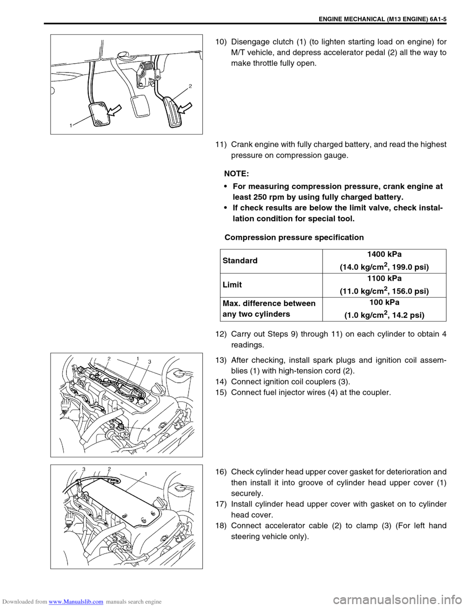
10) Disengage clutch (1) (to lighten starting load on engine) for
M/T vehicle, and depress accelerator pedal (2) all the way to
make throttle fully open.
11) Crank engine with fully charged battery, and read the highest
pressure on compression gauge.
Compression pressure specification
12) Carry out Steps 9) through 11) on each cylinder to obtain 4
readings.
13) After checking, install spark plugs and ignition coil assem-
blies (1) with high-tension cord (2).
14) Connect ignition coil couplers (3).
15) Connect fuel injector wires (4) at the coupler.
16) Check cylinder head upper cover gasket for deterioration and
then install it into groove of cylinder head upper cover (1)
securely.
17) Install cylinder head upper cover with gasket on to cylinder
head cover.
18) Connect accelerator cable (2) to clamp (3) (For left hand
steering vehicle only).
NOTE:
For measuring compression pressure, crank engine at
least 250 rpm by using fully charged battery.
If check results are below the limit valve, check instal-
lation condition for special tool.
Standard1400 kPa
(14.0 kg/cm
2, 199.0 psi)
Limit1100 kPa
(11.0 kg/cm
2, 156.0 psi)
Max. difference between
any two cylinders100 kPa
(1.0 kg/cm
2, 14.2 psi)