2005 SUZUKI JIMNY checking oil
[x] Cancel search: checking oilPage 39 of 687

Downloaded from www.Manualslib.com manuals search engine 0B-8 MAINTENANCE AND LUBRICATION
6) Replenish oil until oil level is brought to FULL level mark on
dipstick. (oil pan and oil filter capacity). The filler inlet is at
the top of the cylinder head cover.
It is recommended to use engine oil of SE, SF, SG, SH, SJ or
SL grade.
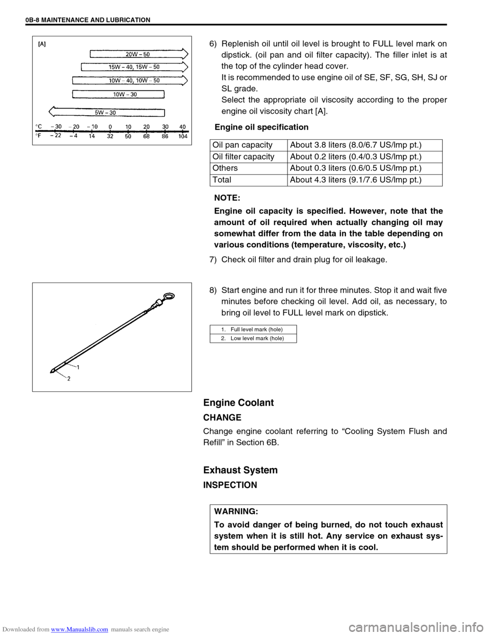
Select the appropriate oil viscosity according to the proper
engine oil viscosity chart [A].
Engine oil specification
7) Check oil filter and drain plug for oil leakage.
8) Start engine and run it for three minutes. Stop it and wait five
minutes before checking oil level. Add oil, as necessary, to
bring oil level to FULL level mark on dipstick.
Engine Coolant
CHANGE
Change engine coolant referring to “Cooling System Flush and
Refill” in Section 6B.
Exhaust System
INSPECTION
Oil pan capacity About 3.8 liters (8.0/6.7 US/lmp pt.)
Oil filter capacity About 0.2 liters (0.4/0.3 US/lmp pt.)
Others About 0.3 liters (0.6/0.5 US/lmp pt.)
Total About 4.3 liters (9.1/7.6 US/lmp pt.)
NOTE:
Engine oil capacity is specified. However, note that the
amount of oil required when actually changing oil may
somewhat differ from the data in the table depending on
various conditions (temperature, viscosity, etc.)
1. Full level mark (hole)
2. Low level mark (hole)
WARNING:
To avoid danger of being burned, do not touch exhaust
system when it is still hot. Any service on exhaust sys-
tem should be performed when it is cool.
Page 47 of 687

Downloaded from www.Manualslib.com manuals search engine 0B-16 MAINTENANCE AND LUBRICATION
Manual Transmission Oil
INSPECTION
1) Inspect transmission case for evidence of oil leakage.
Repair leaky point if any.
2) Make sure that vehicle is placed level for oil level check.
3) Remove level plug (2) of transmission.
4) Check oil level.
Oil level can be checked roughly by means of level plug hole.
That is, if oil flows out of level plug hole or if oil level is found
up to hole when level plug is removed, oil is properly filled.
If oil is found insufficient, pour specified amount of specified
oil.
5) Tighten level plug to specified torque.
Refer to “Maintenance Service” in Section 7A for installation
and tightening torque.
CHANGE
Change transmission oil with new specified oil referring to “Main-
tenance Service” in Section 7A.
Automatic Transmission Fluid
INSPECTION
1) Inspect transmission case for evidence of fluid leakage.
Repair leaky point, if any.
2) Make sure that vehicle is placed level for fluid level check.
3) Check fluid level.
For fluid level checking procedure, refer to “Fluid Level
Check” in Section 7B and be sure to perform it under speci-
fied conditions. If fluid level is low, replenish specified fluid.
CHANGE
1) Inspect transmission case for evidence of fluid leakage.
Repair leaky point, if any.
2) Make sure that vehicle is placed level for fluid level check.
3) Change fluid. For its procedure, refer to “Changing Fluid” in
Section 7B.
1. Dipstick
2.“FULL HOT” mark
3.“LOW HOT” mark
CAUTION:
Use of specified fluid is absolutely necessary.
1. Drain plug
Page 62 of 687

Downloaded from www.Manualslib.com manuals search engine AIR CONDITIONING (OPTIONAL) 1B-1
6F1
6F2
1B
7A
7A1
7B1
7C1
7D
7E
7F
8A
8B
8C
8D
8E
9
10
10A
10B
SECTION 1B
AIR CONDITIONING (OPTIONAL)
CONTENTS
General Description ....................................... 1B-3
Major Components and Location ................. 1B-3
Refrigerant Circulation ................................. 1B-4
Refrigerant Type .......................................... 1B-4
Diagnosis ........................................................ 1B-5
General Diagnosis Table .............................. 1B-5
Abnormal Noise Diagnosis ........................... 1B-7
Abnormal noise from compressor ............ 1B-7
Abnormal noise from magnetic clutch ...... 1B-7
Abnormal noise from tubing ..................... 1B-7
Abnormal noise from condenser .............. 1B-7
Abnormal noise from crankshaft pulley .... 1B-8
Abnormal noise from tension pulley ......... 1B-8
Abnormal noise from A/C evaporator ....... 1B-8
Abnormal noise from blower fan motor .... 1B-8
Quick Checking of Refrigerant Charge......... 1B-9Performance Diagnosis.............................. 1B-10
Performance diagnosis table.................. 1B-12
Detail diagnosis table (Ambient
temperature at 30°C (86°F)) .................. 1B-13
Compressor Drive Belt ............................... 1B-15
Electronical Diagnosis ................................ 1B-16
Wiring Diagram .......................................... 1B-16
A/C System Inspection of ECM and ITS
Circuits ....................................................... 1B-17
Refrigerant Recovery, Evacuating and
Charging ....................................................... 1B-21
Operation Procedure for Refrigerant
Charging .................................................... 1B-21
Recovery .................................................... 1B-22
Replenishing Compressor Oil .................... 1B-22 WARNING:
For vehicles equipped with Supplemental Restraint (Air Bag) System:
Service on and around the air bag system components or wiring must be performed only by an
authorized SUZUKI dealer. Refer to “Air Bag System Components and Wiring Location View” under
“General Description” in air bag system section in order to confirm whether you are performing ser-
vice on or near the air bag system components or wiring. Please observe all WARNINGS and “Ser-
vice Precautions” under “On-Vehicle Service” in air bag system section before performing service
on or around the air bag system components or wiring. Failure to follow WARNINGS could result in
unintentional activation of the system or could render the system inoperative. Either of these two
conditions may result in severe injury.
Technical service work must be started at least 90 seconds after the ignition switch is turned to the
“LOCK” position and the negative cable is disconnected from the battery. Otherwise, the system
may be activated by reserve energy in the Sensing and Diagnostic Module (SDM).
CAUTION:
The air conditioning system of this vehicle uses refrigerant HFC-134a (R-134a).
None of refrigerant, compressor oil and component parts is interchangeable between two types of
A/C: one using refrigerant HFC-134a (R-134a) and the other using refrigerant CFC-12 (R-12).
Be sure to check which refrigerant is used before any service work including inspection and mainte-
nance. For identification between these two types, refer to “Refrigerant Type” in this section.
When replenishing or changing refrigerant and compressor oil and when replacing parts, make sure
that the material or the part to be used is appropriate to the A/C installed in the vehicle being serviced.
Use of incorrect one will result in leakage of refrigerant, damage in parts or other faulty condition.
NOTE:
For basic servicing method of the air conditioning system that is not described in this section, refer to
AIR CONDITIONING BASIC MANUAL (Part number: 99520-02130).
Page 131 of 687

Downloaded from www.Manualslib.com manuals search engine 3B-10 STEERING GEAR BOX (MANUAL TYPE) AND LINKAGE
Tightening Torque Specifications
Required Service Material
Special Tools
Fastening partTightening torque
Nm kg-m lb-ft
Steering gear box oil plug 4 0.4 3.0
Steering gear box adjusting bolt lock nut 30 3.0 22.0
Pitman arm mounting nut 135 13.5 98.0
Steering shaft joint bolt 25 2.5 18.0
Steering gear box nuts and bolt 80 8.0 58.0
Tie rod end nut and drag rod end nut
(knuckle side)43 4.3 31.5
Wheel nut 95 9.5 69.0
Tie rod end lock nut 65 6.5 47.0
Drag rod end nut (pitman arm side) 50 5.0 36.5
MaterialRecommended SUZUKI product
(Part Number)Use
Sealant SUZUKI BOND NO. 1215
(99000-31110)Thread of oil breathing plug
09913-65210 09944-18211
Tie-rod end remover Pinion torque checking socket
Page 154 of 687

Downloaded from www.Manualslib.com manuals search engine STEERING WHEEL AND COLUMN 3C-1
6F1
6F2
6G
6H
6K
7A
3C
7E
7F
7F
8A
8B
8C
8D
8E
9
10
10A
10B
SECTION 3C
STEERING WHEEL AND COLUMN
CONTENTS
General Description ....................................... 3C-2
Diagnosis ........................................................ 3C-3
Inspection and Repair Required
After Accident ............................................... 3C-3
On-Vehicle Service......................................... 3C-3
Service Precautions (For Vehicle with
Air Bag System) ........................................... 3C-3
Diagnosis and servicing ........................... 3C-3
Disabling air bag system .......................... 3C-3
Enabling air bag system ........................... 3C-3
Handling and storage ............................... 3C-3
Disposal.................................................... 3C-3
Drive Air Bag (Inflator) Module (For Vehicle
with Air Bag System) .................................... 3C-4
Steering Wheel ............................................. 3C-5Centering contact coil (for vehicle with
air bag system)......................................... 3C-8
Combination Switch (For Vehicle without
Air Bag System)/Contact Coil and
Combination Switch Assembly (For Vehicle
with Air Bag System).................................... 3C-9
Steering Column Assembly........................ 3C-11
Steering Lock Assembly
(Ignition Switch) ......................................... 3C-15
Steering Lower Shaft ................................. 3C-16
Checking Steering Column for Accident
Damage ......................................................... 3C-18
Tightening Torque Specifications .............. 3C-19
Required Service Material ........................... 3C-19
Special Tool .................................................. 3C-19
WARNING:
For vehicles equipped with Supplemental Restraint (Air Bag) System:
Service on and around the air bag system components or wiring must be performed only by an
authorized SUZUKI dealer. Please observe all WARNINGS and “Service Precautions” under “On-
Vehicle Service” in air bag system section before performing service on or around the air bag sys-
tem components or wiring. Failure to follow WARNINGS could result in unintentional activation of
the system or could render the system inoperative. Either of these two conditions may result in
severe injury.
The procedures in this section must be followed in the order listed to temporarily disable the air
bag system and prevent false diagnostic codes from setting. Failure to follow procedures could
result in possible air bag system activation, personal injury or otherwise unneeded air bag system
repairs.
CAUTION:
When fasteners are removed, always reinstall them at the same location from which they were
removed. If a fastener needs to be replaced, use the correct part number fastener for that application.
If the correct part number fastener is not available, a fastener of equal size and strength (or stronger)
may be used. Fasteners that are not reused, and those requiring thread-locking compound, will be
called out. The correct torque value must be used when installing fasteners that require it. If the above
procedures are not followed, parts or system damage could result.
Page 383 of 687

Downloaded from www.Manualslib.com manuals search engine 6-26 ENGINE GENERAL INFORMATION AND DIAGNOSIS
Excessive engine oil
consumptionSticky piston ring Pistons, piston rings, connecting rods
and cylinders in Section 6A1.
Worn piston and cylinder Pistons, piston rings, connecting rods
and cylinders in Section 6A1.
Worn piston ring groove and ring Pistons, piston rings, connecting rods
and cylinders in Section 6A1.
Improper location of piston ring gap Pistons, piston rings, connecting rods
and cylinders in Section 6A1.
Worn or damaged valve stem seal Valves and cylinder head in Section
6A1.
Worn valve stem Valves and cylinder head in Section
6A1.
Low oil pressure
Improper oil viscosity ITEM1-3 Engine oil and oil filter
change in Section 0B.
Malfunctioning oil pressure switch Oil pressure switch in Section 8.
Clogged oil strainer Oil pan and oil pump strainer in Sec-
tion 6A1.
Functional deterioration of oil pump Oil pump in Section 6A1.
Worn oil pump relief valve Oil pump in Section 6A1.
Excessive clearance in various sliding
partsRefer to Section 6A1.
Engine noise
See NOTE below.Improper valve lash Valve lash in Section 6A1.
Worn valve stem and guide Valves and cylinder head in Section
6A1.
Weak or broken valve spring Valve springs in Section 6A1.
Warped or bent valve Valves and cylinder head in Section
6A1.
Loose camshaft housing bolts Camshaft in Section 6A1.
Worn piston, ring and cylinder bore Pistons and cylinders in Section 6A1.
Worn crankpin bearing Crankpin and connecting rod bearing
in Section 6A1.
Worn crankpin Crankpin and connecting rod bearing
in Section 6A1.
Loose connecting rod nuts Connecting rod in Section 6A1.
Low oil pressure Previously outlined.
Worn crankshaft journal bearing Main bearings, Crankshaft and cylin-
der block in Section 6A1.
Worn crankshaft journal Main bearings, Crankshaft and cylin-
der block in Section 6A1.
Loose lower crankcase (bearing cap) bolts Main bearings, Crankshaft and cylin-
der block in Section 6A1.
Excessive crankshaft thrust play Main bearings, Crankshaft and cylin-
der block in Section 6A1. Condition Possible Cause Reference Item
NOTE:
Before checking the mechanical noise, make sure that :
Ignition timing is properly adjusted.
Specified spark plug is used.
Specified fuel is used.
Page 486 of 687

Downloaded from www.Manualslib.com manuals search engine ENGINE MECHANICAL (M13 ENGINE) 6A1-5
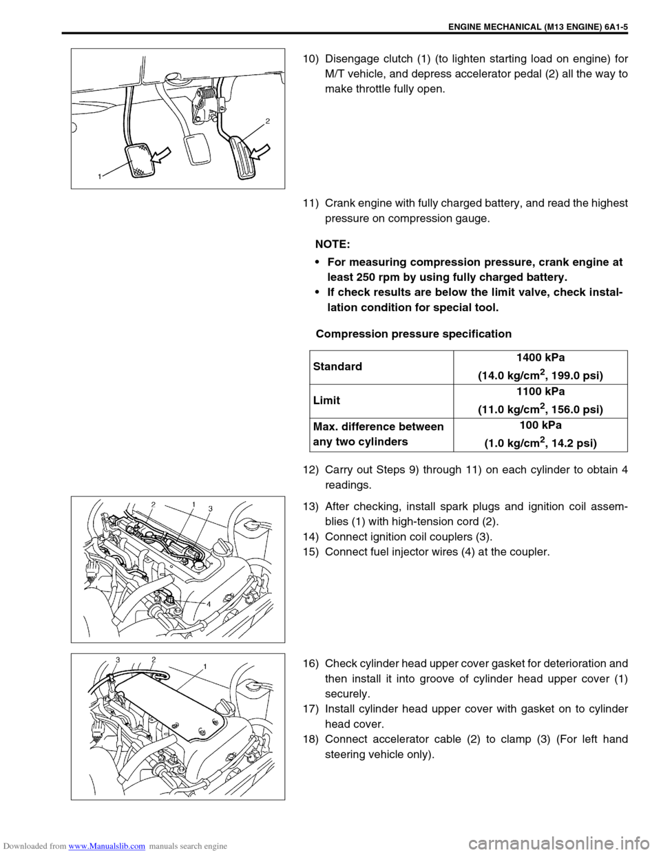
10) Disengage clutch (1) (to lighten starting load on engine) for
M/T vehicle, and depress accelerator pedal (2) all the way to
make throttle fully open.
11) Crank engine with fully charged battery, and read the highest
pressure on compression gauge.
Compression pressure specification
12) Carry out Steps 9) through 11) on each cylinder to obtain 4
readings.
13) After checking, install spark plugs and ignition coil assem-
blies (1) with high-tension cord (2).
14) Connect ignition coil couplers (3).
15) Connect fuel injector wires (4) at the coupler.
16) Check cylinder head upper cover gasket for deterioration and
then install it into groove of cylinder head upper cover (1)
securely.
17) Install cylinder head upper cover with gasket on to cylinder
head cover.
18) Connect accelerator cable (2) to clamp (3) (For left hand
steering vehicle only).
NOTE:
For measuring compression pressure, crank engine at
least 250 rpm by using fully charged battery.
If check results are below the limit valve, check instal-
lation condition for special tool.
Standard1400 kPa
(14.0 kg/cm
2, 199.0 psi)
Limit1100 kPa
(11.0 kg/cm
2, 156.0 psi)
Max. difference between
any two cylinders100 kPa
(1.0 kg/cm
2, 14.2 psi)
Page 488 of 687

Downloaded from www.Manualslib.com manuals search engine ENGINE MECHANICAL (M13 ENGINE) 6A1-7
Oil Pressure Check
Oil level in oil pan.
If oil level is low, add oil up to Full level mark (hole) (1) on oil
level gauge.
Oil quality.
If oil is discolored, or deteriorated, change it.
For particular oil to be used, refer to the table in Section 0B.
Oil leaks.
If leak is found, repair it.
1) Disconnect oil pressure switch coupler (1) and remove oil
pressure switch (2) from cylinder block.
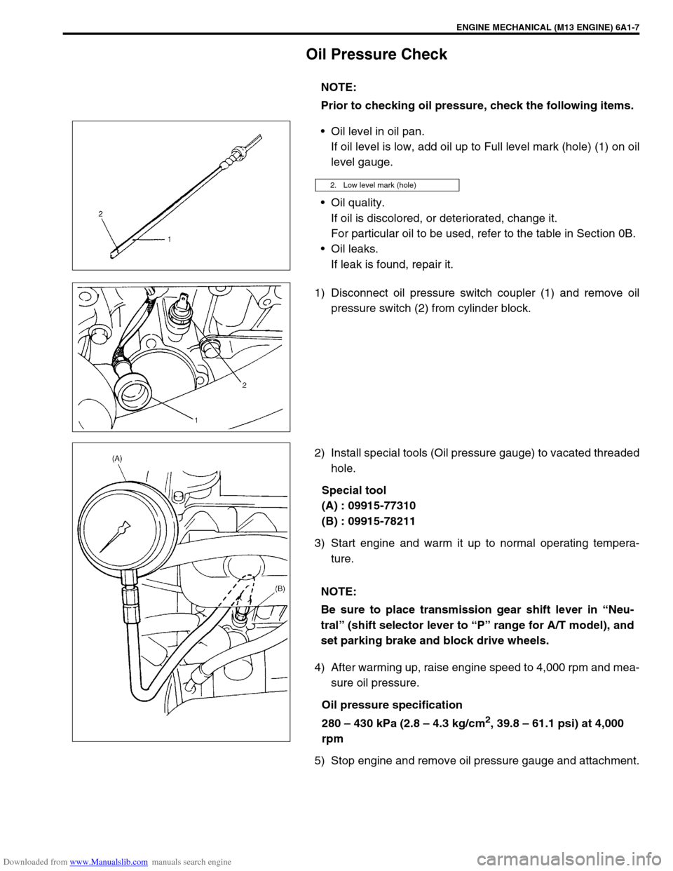
2) Install special tools (Oil pressure gauge) to vacated threaded
hole.
Special tool
(A) : 09915-77310
(B) : 09915-78211
3) Start engine and warm it up to normal operating tempera-
ture.
4) After warming up, raise engine speed to 4,000 rpm and mea-
sure oil pressure.
Oil pressure specification
280 – 430 kPa (2.8 – 4.3 kg/cm
2, 39.8 – 61.1 psi) at 4,000
rpm
5) Stop engine and remove oil pressure gauge and attachment.NOTE:
Prior to checking oil pressure, check the following items.
2. Low level mark (hole)
NOTE:
Be sure to place transmission gear shift lever in “Neu-
tral” (shift selector lever to “P” range for A/T model), and
set parking brake and block drive wheels.