Page 312 of 687

Downloaded from www.Manualslib.com manuals search engine BRAKES 5-51
Rear Brake Hose/Pipe
REMOVAL
1) Raise, suitably support vehicle. Remove wheel if necessary.
2) Clean dirt and foreign material from both hose end or pipe end fittings. Remove brake hose and pipe.
INSTALLATION
1) Install brake hose and pipe by reversing removal procedure, noting the following points.
Fill and maintain brake fluid level in reservoir. Bleed brake system.
2) Perform brake test and check each installed part for fluid leakage.
CAUTION:
Position clamps to white marks on two brake pipes.
Be sure to obtain more than 3 mm (0.118 in.) clearance between axle housing and brake pipe.
Install clamps properly referring to figure below and tighten bolts.
When installing hose, make sure that it has no twist or kink.
T : Top side 2. Rear axle housing 5. Fuel tank 8. Brake pipe (vehicle with LSPV)
R : Right side 3. Rear wheel cylinder 6. Chassis frame a-b: Clamp
1. Clamp 4. LSPV (if equipped) 7. Fuel pipe Tightening torque
Page 599 of 687

Downloaded from www.Manualslib.com manuals search engine 6C-4 ENGINE FUEL
On-Vehicle Service
Before work, refer to “Precaution on Fuel System Service” in Sec-
tion 6.
Fuel Lines
Due to the fact that fuel feed line is under high pressure, use spe-
cial care when servicing it.
INSPECTION
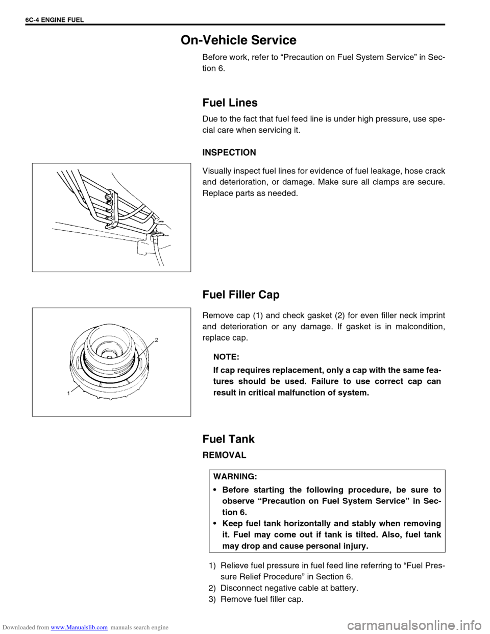
Visually inspect fuel lines for evidence of fuel leakage, hose crack
and deterioration, or damage. Make sure all clamps are secure.
Replace parts as needed.
Fuel Filler Cap
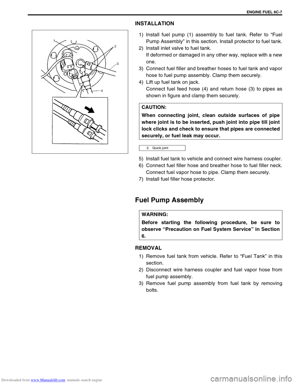
Remove cap (1) and check gasket (2) for even filler neck imprint
and deterioration or any damage. If gasket is in malcondition,
replace cap.
Fuel Tank
REMOVAL
1) Relieve fuel pressure in fuel feed line referring to “Fuel Pres-
sure Relief Procedure” in Section 6.
2) Disconnect negative cable at battery.
3) Remove fuel filler cap.
NOTE:
If cap requires replacement, only a cap with the same fea-
tures should be used. Failure to use correct cap can
result in critical malfunction of system.
WARNING:
Before starting the following procedure, be sure to
observe “Precaution on Fuel System Service” in Sec-
tion 6.
Keep fuel tank horizontally and stably when removing
it. Fuel may come out if tank is tilted. Also, fuel tank
may drop and cause personal injury.
Page 602 of 687

Downloaded from www.Manualslib.com manuals search engine ENGINE FUEL 6C-7
INSTALLATION
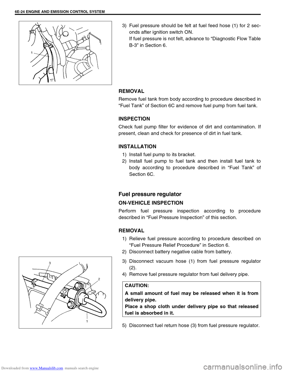
1) Install fuel pump (1) assembly to fuel tank. Refer to “Fuel
Pump Assembly” in this section. Install protector to fuel tank.
2) Install inlet valve to fuel tank.
If deformed or damaged in any other way, replace with a new
one.
3) Connect fuel filler and breather hoses to fuel tank and vapor
hose to fuel pump assembly. Clamp them securely.
4) Lift up fuel tank on jack.
Connect fuel feed hose (4) and return hose (3) to pipes as
shown in figure and clamp them securely.
5) Install fuel tank to vehicle and connect wire harness coupler.
6) Connect fuel filler hose and breather hose to fuel filler neck.
Connect fuel vapor hose to pipe. Clamp them securely.
7) Install fuel filler hose protector.
Fuel Pump Assembly
REMOVAL
1) Remove fuel tank from vehicle. Refer to “Fuel Tank” in this
section.
2) Disconnect wire harness coupler and fuel vapor hose from
fuel pump assembly.
3) Remove fuel pump assembly from fuel tank by removing
bolts. CAUTION:
When connecting joint, clean outside surfaces of pipe
where joint is to be inserted, push joint into pipe till joint
lock clicks and check to ensure that pipes are connected
securely, or fuel leak may occur.
2. Quick joint
WARNING:
Before starting the following procedure, be sure to
observe “Precaution on Fuel System Service” in Section
6.
Page 604 of 687

Downloaded from www.Manualslib.com manuals search engine ENGINE FUEL 6C-9
INSTALLATION
1) Clean mating surfaces of fuel pump assembly and fuel tank.
2) Install new gasket (2) and plate (3) to fuel pump assembly
(1) then install fuel pump assembly to fuel tank.
Tightening torque
Fuel pump assembly bolts (a) : 10 N·m (1.0 kg-m, 7.5 lb-ft)
3) Connect wire harness coupler (2) and fuel vapor hose (3) to
fuel pump assembly (1).
4) Install fuel tank to vehicle. Refer to “Fuel Tank” in this sec-
tion. CAUTION:
While removing fuel level gauge, do not contact resis-
tor plate (2) or deform arm (3). It may cause fuel level
gauge to fail.
When removing grommet from fuel tube or bracket sub
assembly, be very careful not to cause damage to
grommet installed section (sealed section in bore).
Should it be damaged, replace it with new one, or fuel
will leak from that part.
NOTE:
When removing fuel level gauge, press snap-fit part (1)
and slide it in the arrow direction as shown in figure.
When installing fuel level gauge to housing, fit protru-
sion (4) of fuel level gauge in groove (5) in housing and
slide it up till lug (6) fits in window (7) securely. Refer to
figure shown.
[A] : Removal
[B] : Installation
Page 629 of 687

Downloaded from www.Manualslib.com manuals search engine 6E-24 ENGINE AND EMISSION CONTROL SYSTEM
3) Fuel pressure should be felt at fuel feed hose (1) for 2 sec-
onds after ignition switch ON.
If fuel pressure is not felt, advance to “Diagnostic Flow Table
B-3” in Section 6.
REMOVAL
Remove fuel tank from body according to procedure described in
“Fuel Tank” of Section 6C and remove fuel pump from fuel tank.
INSPECTION
Check fuel pump filter for evidence of dirt and contamination. If
present, clean and check for presence of dirt in fuel tank.
INSTALLATION
1) Install fuel pump to its bracket.
2) Install fuel pump to fuel tank and then install fuel tank to
body according to procedure described in “Fuel Tank” of
Section 6C.
Fuel pressure regulator
ON-VEHICLE INSPECTION
Perform fuel pressure inspection according to procedure
described in “Fuel Pressure Inspection” of this section.
REMOVAL
1) Relieve fuel pressure according to procedure described on
“Fuel Pressure Relief Procedure” in Section 6.
2) Disconnect battery negative cable from battery.
3) Disconnect vacuum hose (1) from fuel pressure regulator
(2).
4) Remove fuel pressure regulator from fuel delivery pipe.
5) Disconnect fuel return hose (3) from fuel pressure regulator.
CAUTION:
A small amount of fuel may be released when it is from
delivery pipe.
Place a shop cloth under delivery pipe so that released
fuel is absorbed in it.