Page 28 of 687

Downloaded from www.Manualslib.com manuals search engine GENERAL INFORMATION 0A-23
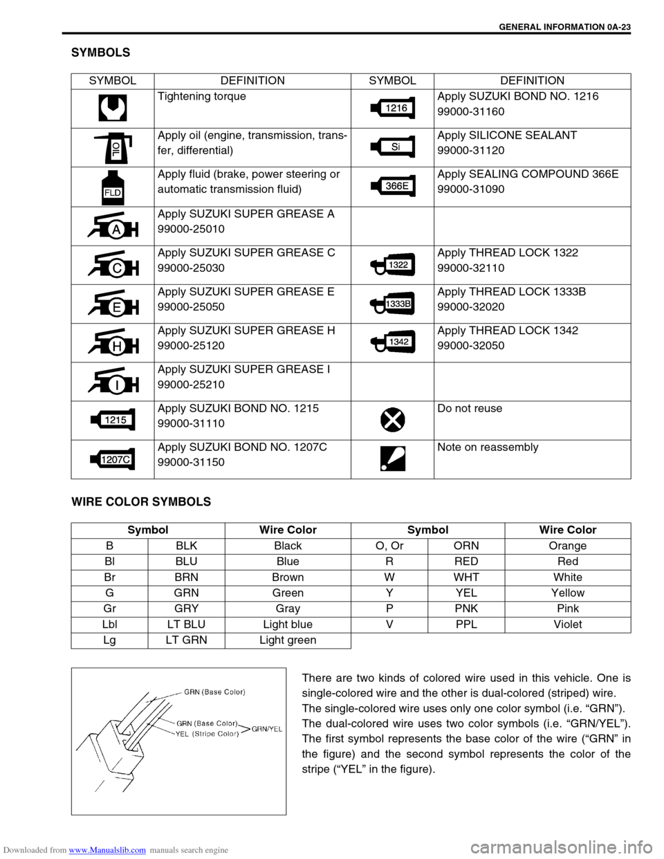
SYMBOLS
WIRE COLOR SYMBOLS
There are two kinds of colored wire used in this vehicle. One is
single-colored wire and the other is dual-colored (striped) wire.
The single-colored wire uses only one color symbol (i.e. “GRN”).
The dual-colored wire uses two color symbols (i.e. “GRN/YEL”).
The first symbol represents the base color of the wire (“GRN” in
the figure) and the second symbol represents the color of the
stripe (“YEL” in the figure). SYMBOL DEFINITION SYMBOL DEFINITION
Tightening torque Apply SUZUKI BOND NO. 1216
99000-31160
Apply oil (engine, transmission, trans-
fer, differential)Apply SILICONE SEALANT
99000-31120
Apply fluid (brake, power steering or
automatic transmission fluid)Apply SEALING COMPOUND 366E
99000-31090
Apply SUZUKI SUPER GREASE A
99000-25010
Apply SUZUKI SUPER GREASE C
99000-25030Apply THREAD LOCK 1322
99000-32110
Apply SUZUKI SUPER GREASE E
99000-25050Apply THREAD LOCK 1333B
99000-32020
Apply SUZUKI SUPER GREASE H
99000-25120Apply THREAD LOCK 1342
99000-32050
Apply SUZUKI SUPER GREASE I
99000-25210
Apply SUZUKI BOND NO. 1215
99000-31110Do not reuse
Apply SUZUKI BOND NO. 1207C
99000-31150Note on reassembly
Symbol Wire Color Symbol Wire Color
B BLK Black O, Or ORN Orange
Bl BLU Blue R RED Red
Br BRN Brown W WHT White
GGRN Green Y YEL Yellow
Gr GRY Gray P PNK Pink
Lbl LT BLU Light blue V PPL Violet
Lg LT GRN Light green
Page 330 of 687

Downloaded from www.Manualslib.com manuals search engine ANTILOCK BRAKE SYSTEM (ABS) 5E-13
TERMINAL CIRCUIT
A1 Idle up signal
A2 Stop lamp switch
A3 Right front wheel speed sensor (+)
A4 Right front wheel speed sensor (–)
A5–
A6 Right rear wheel speed sensor (–)
A7 Right rear wheel speed sensor (+)
A8–
A9–
A10–
A11 G sensor signal
A12 Diagnosis switch terminal
A13 G sensor ground
A14“ABS” warning lamp
A15 Left front wheel speed sensor (+)
A16 Left front wheel speed sensor (–)
A17 4WD switch (for 4WD model only)
A18 Ignition switch
A19 Left rear wheel speed sensor (+)
A20 Left rear wheel speed sensor (–)
A21 Data link connector
A22 Ground (for ABS pump motor)
A23 ABS pump motor power supply
A24 Ground (for ABS control module)
A25 Solenoid valve power supply
Wire color
B : Black G/W : Green / White R/W : Red / White
B/BI : Black / Blue Lg/B : Light green / Black W/Bl : White / Blue
B/W : Black / White Lg/R : Light green / Red W/G : White / Green
B/Or : Black / Orange Or : Orange W/R : White / Red
Bl : Blue Or/B : Orange / Black Y : Yellow
Bl/W : Blue / White P/B : Pink / Black Y/B : Yellow / Black
G : Green P/G : Pink / Green
G/B : Green / Black R/Bl : Red / Blue
Page 331 of 687

Downloaded from www.Manualslib.com manuals search engine 5E-14 ANTILOCK BRAKE SYSTEM (ABS)
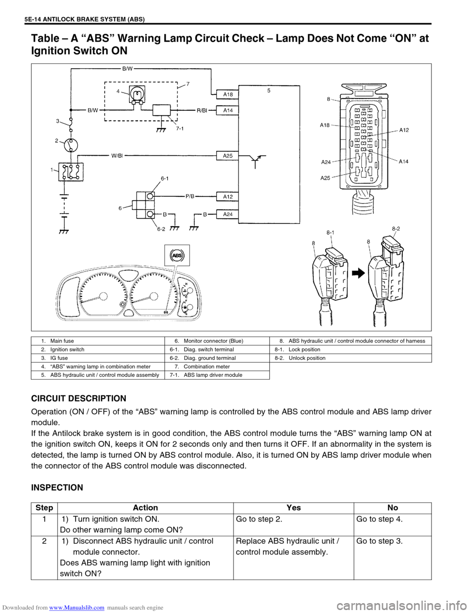
Table – A “ABS” Warning Lamp Circuit Check – Lamp Does Not Come “ON” at
Ignition Switch ON
CIRCUIT DESCRIPTION
Operation (ON / OFF) of the “ABS” warning lamp is controlled by the ABS control module and ABS lamp driver
module.
If the Antilock brake system is in good condition, the ABS control module turns the “ABS” warning lamp ON at
the ignition switch ON, keeps it ON for 2 seconds only and then turns it OFF. If an abnormality in the system is
detected, the lamp is turned ON by ABS control module. Also, it is turned ON by ABS lamp driver module when
the connector of the ABS control module was disconnected.
INSPECTION
1. Main fuse 6. Monitor connector (Blue) 8. ABS hydraulic unit / control module connector of harness
2. Ignition switch 6-1. Diag. switch terminal 8-1. Lock position
3. IG fuse 6-2. Diag. ground terminal 8-2. Unlock position
4.“ABS” warning lamp in combination meter 7. Combination meter
5. ABS hydraulic unit / control module assembly 7-1. ABS lamp driver module
Step Action Yes No
1 1) Turn ignition switch ON.
Do other warning lamp come ON?Go to step 2. Go to step 4.
2 1) Disconnect ABS hydraulic unit / control
module connector.
Does ABS warning lamp light with ignition
switch ON?Replace ABS hydraulic unit /
control module assembly.Go to step 3.
Page 520 of 687

Downloaded from www.Manualslib.com manuals search engine ENGINE MECHANICAL (M13 ENGINE) 6A1-39
INSTALLATION
1) Check that match marks (1) on intake and exhaust camshaft
timing sprockets are in match with notches (2) on cylinder
head as shown in figure.
2) Set key (3) and turn crankshaft to position key on upside of
crankshaft.
3) Install timing chain by aligning dark blue plate (1) of timing
chain and mark (2) on camshaft timing sprocket and then
aligning dark blue plate (3) and triangle mark (4) as shown in
figure.
4) Fit crankshaft timing sprocket to timing chain by aligning gold
plate (5) of timing chain and mark (6) on crankshaft timing
sprocket. Then install crankshaft timing sprocket fitted with
chain to crankshaft.
5) Apply engine oil to sliding surface of timing chain No.1 guide
(1) and install it as shown in figure.
Tighten guide bolts to specified torque.
Tightening torque
Timing chain No.1 guide bolts
(a) : 9 N·m (0.9 kg-m, 6.5 lb-ft) CAUTION:
After timing chain is removed, never turn crankshaft and
camshafts independently more than such an extent (“a”,
“b”) as shown in figure.
If turned, interference may occur between piston and
valves and valves themselves, and parts related to piston
and valves may be damaged.
“a” :90°5. Crankshaft allowable turning range.
By key on crankshaft, within 90° from top on both right and left.
“b” :15°4. Camshaft (IN and EX) allowable turning range.
By marks on camshaft timing sprocket within 15° from notches on
cylinder head on both right and left.
Page 521 of 687

Downloaded from www.Manualslib.com manuals search engine 6A1-40 ENGINE MECHANICAL (M13 ENGINE)
6) Apply engine oil to sliding surface of chain tensioner (1) and
install chain tensioner and spacer.
Tighten tensioner bolt to specified torque
Tightening torque
Timing chain tensioner bolt
(a) : 22 N·m (2.2 kg-m, 16.0 lb-ft)
7) Check that match marks (1) on intake and exhaust camshaft
timing sprockets are in match with dark blue plates (2) of tim-
ing chain and match mark (3) on crankshaft timing sprocket
is in match with gold plate (4) of timing chain.
8) Screw in plunger (1) by turning timing chain tensioner
adjuster (2) in arrow direction and install a retainer (3) (wire)
to hold plunger in place.
9) Install timing chain tensioner adjuster assembly (1) with a
retainer (2).
Tighten adjuster bolts to specified torque and then remove a
retainer from chain tensioner adjuster assembly.
Tightening torque
Timing chain tensioner adjuster bolts
(a) : 11 N·m (1.1 kg-m, 8.0 lb-ft)
221
3
4