Page 80 of 687

Downloaded from www.Manualslib.com manuals search engine AIR CONDITIONING (OPTIONAL) 1B-19
ECM VOLTAGE VALUES TABLE FOR RELATION OF A/C CONTROL
Terminal Wire CircuitMeasurement
groundNormal value Condition
E18-1 PCompressor
magnet clutch
outputGround to
engine (Fig B)10 – 14 voltBlower fan motor switch and A/C
switch ON with engine running
0 – 1 voltsExcept the above-mentioned condi-
tion with engine running
E18-5 Bl/BMain power sup-
ply for ECMGround to
engine (Fig B)10 – 14 voltsIgnition switch ON with engine
stopped
E18-6 Bl/BMain power sup-
ply for ECMGround to
engine (Fig B)10 – 14 voltsIgnition switch ON with engine
stopped
E18-10 Bl Main relay driveGround to
engine (Fig B)0.5 – 1.2 voltIgnition switch ON with engine
stopped
0 volts Ignition switch OFF
E18-16 G/W A/C switch inputGround to
engine (Fig B)12 – 15 voltsBlower fan motor switch or A/C switch
OFF with engine running
0 – 1 voltBlower fan motor switch and A/C
switch ON with engine running
12 – 15 voltsWithin several seconds after operate
transfer lever between 2WD and 4WD
with above condition
E18-18 P/BCompressor
cooling fan relay
outputGround to
engine (Fig B)0 – 1 voltBlower fan motor switch and A/C
switch ON or engine coolant tempera-
ture at more than 110 °C (230 °F) with
engine running.
12 – 15 voltsExcept the above-mentioned condi-
tion with engine running
E18-20 B/BlSensor ground
for A/C evapora-
torGround to
body (Fig A)–0.5 – 0 volt Engine running
E18-24 Bl/YBlower fan
speed inputGround to
engine (Fig B)0 – 1 voltBlower fan motor switch 2nd or 3rd
with engine running
4 – 7 voltsBlower fan motor switch 1st with
engine running
12 – 15 voltsBlower fan motor switch and A/C
switch OFF with engine running
E19-1 BMain ground for
ECMGround to
engine (Fig A)–0.5 – 1 volt Engine running
E19-2 B/RECM ground for
power circuitGround to
engine (Fig A)–0.5 – 1 volt Engine running
E19-3 B/RECM ground for
power circuitGround to
engine (Fig A)–0.5 – 1 volt Engine running
E19-10 B/BlSensor ground
for ECT sensorGround to
body (Fig A)–0.5 – 1 volt Engine running
Page 81 of 687

Downloaded from www.Manualslib.com manuals search engine 1B-20 AIR CONDITIONING (OPTIONAL)
E19-14 G/BECT sensor
inputGround to
engine (Fig B)0.73 – 0.83 volts
(315 – 355 Ω)Engine coolant temperature at
approximately 80 °C (176 °F) with
engine running
0.35 – 0.45 volts
(145 – 165 Ω)Engine coolant temperature at
approximately 110 °C (230 °F) with
engine running
*If the temperature is more than
113 °C (235 °F), compressor should
be stop (come back at less than
111 °C (232 °F)
E19-27 W/RA/C evaporator
thermistor tem-
perature inputGround to
engine (Fig B)2.0 – 2.3 volts
(1800 – 2200 Ω)Evaporator thermistor temperature at
approximately 25 °C (77 °F) with
engine running
3.5 – 3.6 volts
(6300 – 7000 Ω)Evaporator thermistor temperature at
approximately 0 °C (32 °F) with
engine running
*If the temperature is less than
approximately 2.5 °C (36.5 °F), com-
pressor cooling fan should be stop
(come back at less than approxi-
mately 4 °C (39.2 °F) Terminal Wire CircuitMeasurement
groundNormal value Condition
Page 92 of 687

Downloaded from www.Manualslib.com manuals search engine AIR CONDITIONING (OPTIONAL) 1B-31
Condenser Assembly
INSPECTION
Check the following.
Check clog of condenser fins.
If, any clogs are found, condenser fins should be washed
with water, and should be dried with compressed air.
Check condenser fins for leakage and breakage.
If any defects are found, repair or replace condenser.
Check condenser fittings for leakage.
If any defects are found, repair or replace condenser.
REMOVAL
1) Disconnect negative (–) cable at battery.
2) Recover refrigerant from A/C system by referring to “Recov-
ery” in this section.
3) Remove front bumper referring to “Front Bumper” in Section
8.
4) Disconnect A/C condenser cooling fan motor and dual pres-
sure switch connectors.
5) Remove radiator mounting bolts.
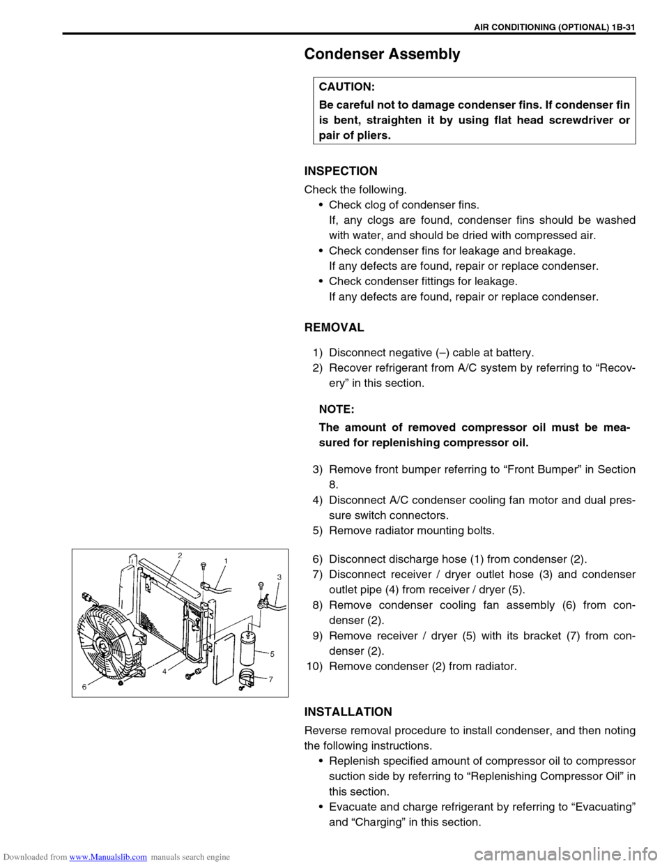
6) Disconnect discharge hose (1) from condenser (2).
7) Disconnect receiver / dryer outlet hose (3) and condenser
outlet pipe (4) from receiver / dryer (5).
8) Remove condenser cooling fan assembly (6) from con-
denser (2).
9) Remove receiver / dryer (5) with its bracket (7) from con-
denser (2).
10) Remove condenser (2) from radiator.
INSTALLATION
Reverse removal procedure to install condenser, and then noting
the following instructions.
Replenish specified amount of compressor oil to compressor
suction side by referring to “Replenishing Compressor Oil” in
this section.
Evacuate and charge refrigerant by referring to “Evacuating”
and “Charging” in this section. CAUTION:
Be careful not to damage condenser fins. If condenser fin
is bent, straighten it by using flat head screwdriver or
pair of pliers.
NOTE:
The amount of removed compressor oil must be mea-
sured for replenishing compressor oil.
Page 94 of 687
Downloaded from www.Manualslib.com manuals search engine AIR CONDITIONING (OPTIONAL) 1B-33
Condenser Cooling Fan Assembly
ASSEMBLY
INSPECTION
1) Check continuity between each two terminals about the con-
denser cooling fan motor (1).
If check results are no continuity, replace condenser cooling
fan motor.
2) Connect battery to condenser cooling fan motor as shown in
figure, then check that the condenser cooling fan motor
operates smoothly.
Reference current of condenser cooling fan motor
approximately 7.5 A at 12 V
REMOVAL
1) Remove front bumper.
2) Disconnect condenser cooling fan motor connector (1).
3) Remove radiator mounting bolts.
4) Remove condenser cooling fan assembly (2) from con-
denser (3).
INSTALLATION
Reverse removal procedure for installation.CAUTION:
Be careful not to damage condenser fins. If condenser fin
is bent, straighten condenser fin by using flat head
screwdriver or pair of pliers.
Page 95 of 687
Downloaded from www.Manualslib.com manuals search engine 1B-34 AIR CONDITIONING (OPTIONAL)
Cooling Unit (Evaporator)
REMOVAL
1) Disconnect negative (–) cable at battery.
2) Recover refrigerant from A/C system by referring to “Recov-
ery” in this section. CAUTION:
Be careful not to damage A/C evaporator fins. If A/C evaporator fin is bent, straighten A/C evaporator
fin by using flat head screwdriver or pair of pliers.
1. A/C evaporator 3. Expansion valve 5. Packing 7. O-ring
2. A/C evaporator thermistor
(A/C evaporator temperature sensor)4. Evaporator case 6. Air inlet door 8. Door link
NOTE:
The amount of removed compressor oil must be mea-
sured for replenishing compressor oil.
Page 96 of 687
Downloaded from www.Manualslib.com manuals search engine AIR CONDITIONING (OPTIONAL) 1B-35
3) Drain engine coolant and disconnect heater hoses (1) from
heater unit.
4) Disable air bag system referring to “Disabling Air Bag Sys-
tem” in Section 10B (if equipped).
5) Remove attaching bolt (1).
6) Disconnect suction hose (2) and receiver / dryer outlet pipe
(3) from expansion valve (4).
7) Remove instrument panel referring to “Instrument Panel” in
Section 9.
8) Remove cooling unit (1) with heater unit (2) from vehicle
body.
9) Remove cooling unit (1) from heater unit (2).
INSPECTION
Check the following.
Check clog of A/C evaporator fins.
If any clogs are found, A/C evaporator fins should be
washed with water, and should be dried with compressed
air.
Check A/C evaporator fins for leakage and breakage.
If any defects are found, repair or replace A/C evaporator.
Check A/C evaporator fittings for leakage.
If any defects are found, repair or replace A/C evaporator.
Page 97 of 687
Downloaded from www.Manualslib.com manuals search engine 1B-36 AIR CONDITIONING (OPTIONAL)
INSTALLATION
Reverse removal procedure to install cooling unit, and then noting
the following instructions.
If A/C evaporator thermistor removed, its should be rein-
stalled in original position.
Install uniformly the packing (1) to installation hole.
Replenish specified amount of compressor oil to compressor
suction side by referring to “Replenishing Compressor Oil” in
this section.
Evacuate and charge refrigerant by referring to “Evacuating”
and “Charging” in this section.
Adjust mode control cable, temperature control cable and
fresh air control cable by referring to “Heater Control Lever
Assembly” in Section 1A.
Enable air bag system referring to “Enable Air Bag System”
in Section 10B. (if equipped)
Fill engine coolant to radiator, referring to “Cooling System
Flush and Refill” in Section 6B.
Page 100 of 687

Downloaded from www.Manualslib.com manuals search engine AIR CONDITIONING (OPTIONAL) 1B-39
A/C Switch
REMOVAL AND INSTALLATION
Refer to “Heater Control Lever Assembly” in Section 1A.
INSPECTION
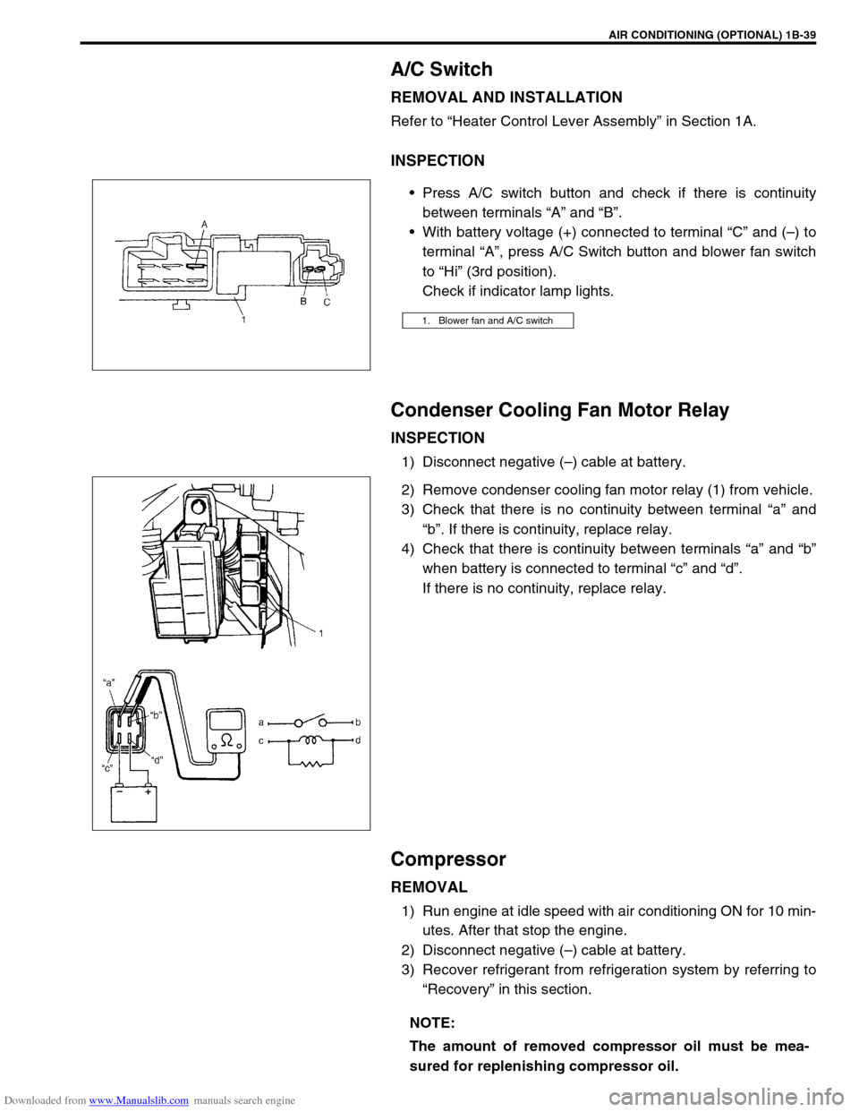
Press A/C switch button and check if there is continuity
between terminals “A” and “B”.
With battery voltage (+) connected to terminal “C” and (–) to
terminal “A”, press A/C Switch button and blower fan switch
to “Hi” (3rd position).
Check if indicator lamp lights.
Condenser Cooling Fan Motor Relay
INSPECTION
1) Disconnect negative (–) cable at battery.
2) Remove condenser cooling fan motor relay (1) from vehicle.
3) Check that there is no continuity between terminal “a” and
“b”. If there is continuity, replace relay.
4) Check that there is continuity between terminals “a” and “b”
when battery is connected to terminal “c” and “d”.
If there is no continuity, replace relay.
Compressor
REMOVAL
1) Run engine at idle speed with air conditioning ON for 10 min-
utes. After that stop the engine.
2) Disconnect negative (–) cable at battery.
3) Recover refrigerant from refrigeration system by referring to
“Recovery” in this section.
1. Blower fan and A/C switch
NOTE:
The amount of removed compressor oil must be mea-
sured for replenishing compressor oil.