2005 SUZUKI JIMNY ball joint
[x] Cancel search: ball jointPage 45 of 687

Downloaded from www.Manualslib.com manuals search engine 0B-14 MAINTENANCE AND LUBRICATION
3) Rotate tires.
For details, refer to “Tire Rotation” in Section 3F.
WHEEL DISCS INSPECTION
Inspect each wheel disc for dents, distortion and cracks. A disc in
badly damaged condition must be replaced.
WHEEL BEARING INSPECTION
1) Check front wheel bearing for wear, damage, abnormal
noise or rattles. For details, refer to “Wheel Disc, Nut and
Bearing Check” in Section 3D.
2) Check rear wheel bearing for wear, damage, abnormal noise
or rattles. For details, refer to “Wheel Disc, Nut and Bearing
Check” in Section 3E.
Suspension System
INSPECTION
Check suspension bolts and nuts for tightness and retighten them
as necessary.
Repair or replace defective parts, if any.
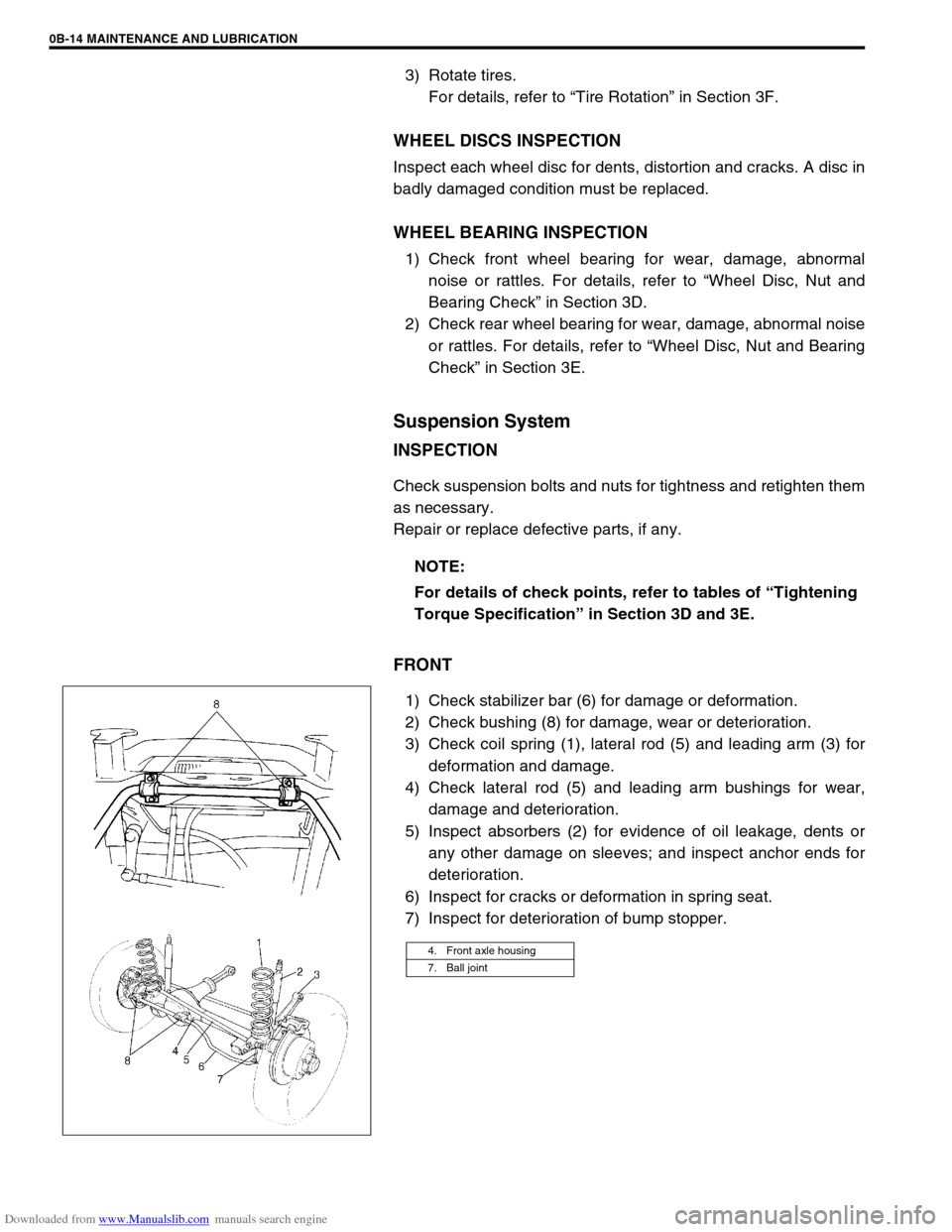
FRONT
1) Check stabilizer bar (6) for damage or deformation.
2) Check bushing (8) for damage, wear or deterioration.
3) Check coil spring (1), lateral rod (5) and leading arm (3) for
deformation and damage.
4) Check lateral rod (5) and leading arm bushings for wear,
damage and deterioration.
5) Inspect absorbers (2) for evidence of oil leakage, dents or
any other damage on sleeves; and inspect anchor ends for
deterioration.
6) Inspect for cracks or deformation in spring seat.
7) Inspect for deterioration of bump stopper.NOTE:
For details of check points, refer to tables of “Tightening
Torque Specification” in Section 3D and 3E.
4. Front axle housing
7. Ball joint
Page 112 of 687

Downloaded from www.Manualslib.com manuals search engine STEERING, SUSPENSION, WHEELS AND TIRES 3-3
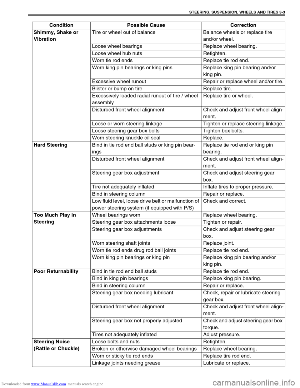
Shimmy, Shake or
VibrationTire or wheel out of balance Balance wheels or replace tire
and/or wheel.
Loose wheel bearings Replace wheel bearing.
Loose wheel hub nuts Retighten.
Worn tie rod ends Replace tie rod end.
Worn king pin bearings or king pins Replace king pin bearing and/or
king pin.
Excessive wheel runout Repair or replace wheel and/or tire.
Blister or bump on tire Replace tire.
Excessively loaded radial runout of tire / wheel
assemblyReplace tire or wheel.
Disturbed front wheel alignment Check and adjust front wheel align-
ment.
Loose or worn steering linkage Tighten or replace steering linkage.
Loose steering gear box bolts Tighten box bolts.
Worn steering knuckle oil seal Replace.
Hard Steering
Bind in tie rod end ball studs or king pin bear-
ingsReplace tie rod end or king pin
bearing.
Disturbed front wheel alignment Check and adjust front wheel align-
ment.
Steering gear box adjustment Check and adjust steering gear
box.
Tire not adequately inflated Inflate tires to proper pressure.
Bind in steering column Repair or replace.
Low fluid level, loose drive belt or malfunction of
power steering system (if equipped with P/S)Check and correct.
Too Much Play in
SteeringWheel bearings worn Replace wheel bearing.
Steering gear box attachments loose Tighten or repair.
Steering gear box adjustments Check and adjust steering gear
box.
Worn steering shaft joints Replace joint.
Worn tie rod ends drug rod ball joints Replace tie rod end.
Worn king pin bearings or king pin Replace king pin bearing and/or
king pin.
Poor Returnability
Bind in tie rod end ball studs Replace tie rod end.
Bind in king pin bearings Replace king pin bearing.
Bind in steering column Repair or replace.
Steering gear box needing lubricant Check, repair or lubricate steering
gear box.
Disturbed front wheel alignment Check and adjust front wheel align-
ment.
Steering gear box not properly adjusted Check and adjust steering gear box
torque.
Tires not adequately inflated Adjust pressure.
Steering Noise
(Rattle or Chuckle)Loose bolts and nuts Retighten.
Broken or otherwise damaged wheel bearings Replace wheel bearing.
Worn or sticky tie rod ends Replace tire rod end.
Linkage joints needing grease Lubricate or replace. Condition Possible Cause Correction
Page 113 of 687

Downloaded from www.Manualslib.com manuals search engine 3-4 STEERING, SUSPENSION, WHEELS AND TIRES
Abnormal Noise,
Front EndWorn, sticky or loose tie rod ends, drug rod ball
joints, king pin bearings or axle shaft jointsReplace tie rod end, king pin bear-
ing or axle shaft joint.
Damaged shock absorbers or mountings Replace or repair.
Worn leading arm bushings Replace.
Worn stabilizer bar bushings Replace.
Worn Iateral rod bushings Replace.
Loose stabilizer bar Tighten bolts or replace bushes.
Loose wheel nuts Tighten wheel nuts.
Loose suspension bolts or nuts Tighten suspension bolts or nuts.
Broken or otherwise damaged wheel bearings Replace wheel bearing.
Broken suspension springs Replace spring.
Wander or Poor
Steering StabilityMismatched or uneven tires Replace tire or inflate tires to
proper pressure.
Loose king pin bearings and tie rod ends Replace king pin bearing or tie rod
end.
Faulty shock absorbers or mounting Replace absorber or repair mount-
ing.
Loose stabilizer bar Tighten or replace stabilizer bar or
bushes.
Broken or sagging springs Replace spring.
Steering gear box not properly adjusted Check or adjust steering gear box
torque.
Front wheel alignment Check and adjust front wheel align-
ment.
Erratic Steering when
BrakingWorn wheel bearings Replace wheel bearing.
Broken or sagging springs Replace spring.
Leaking wheel cylinder or caliper Repair or replace wheel cylinder or
caliper.
Warped discs Replace brake disc.
Badly worn brake linings Replace brake shoe lining.
Drum is out of round in some brakes Replace brake drum.
Wheel tires are inflated unequally Inflate tires to proper pressure.
Defective wheel cylinders Replace or repair wheel cylinder.
Disturbed front wheel alignment Check front wheel alignment
Ride Too Soft
Faulty shock absorber Replace shock absorber.
Suspension bottoms
Overloaded Check loading.
Faulty shocks absorber Replace shock absorber.
Incorrect, broken or sagging springs Replace spring.
Body Leans or Sways
in CornersLoose stabilizer bar Tighten stabilizer bar bolts or
replace bushes.
Faulty shocks absorbers or mounting Replace shock absorber or tighten
mounting.
Broken or sagging springs Replace spring.
Overloaded Check loading.
Cupped Tires
Worn wheel bearings Replace wheel bearing.
Excessive tire or wheel run-out Replace tire or wheel disc.
Tire out of balance Adjust tire balance. Condition Possible Cause Correction
Page 124 of 687

Downloaded from www.Manualslib.com manuals search engine STEERING GEAR BOX (MANUAL TYPE) AND LINKAGE 3B-3
Diagnosis
Diagnosis Table
Refer to “Diagnosis Table” in Section 3.
Steering Wheel Play Check
Check steering wheel for play and rattle, holding vehicle in
straight forward condition on ground.
Steering wheel play
“a” : 10 – 30 mm (0.4 – 1.2 in.)
If play is not within specification, inspect for the following. If found
defective, replace.
Wear of tie rod end ball stud.
Wear of king pin bearing
Wear of steering shaft joint.
Loosely install or joined parts.
Wear of steering rack / sector gear.
Tie Rod And Drag Rod Check
Inspect deformation or damage. Replace any defective part.
INSPECTION
1) Inspect for play in tie rod end ball joint (1). If found defective,
replace.
2) Inspect boot (2) for tear. If even a small tear is noted, replace
with new one.
Page 128 of 687

Downloaded from www.Manualslib.com manuals search engine STEERING GEAR BOX (MANUAL TYPE) AND LINKAGE 3B-7
INSTALLATION
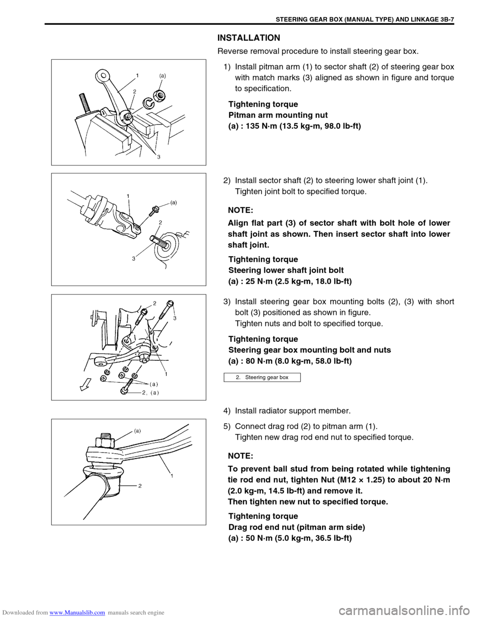
Reverse removal procedure to install steering gear box.
1) Install pitman arm (1) to sector shaft (2) of steering gear box
with match marks (3) aligned as shown in figure and torque
to specification.
Tightening torque
Pitman arm mounting nut
(a) : 135 N·m (13.5 kg-m, 98.0 lb-ft)
2) Install sector shaft (2) to steering lower shaft joint (1).
Tighten joint bolt to specified torque.
Tightening torque
Steering lower shaft joint bolt
(a) : 25 N·m (2.5 kg-m, 18.0 lb-ft)
3) Install steering gear box mounting bolts (2), (3) with short
bolt (3) positioned as shown in figure.
Tighten nuts and bolt to specified torque.
Tightening torque
Steering gear box mounting bolt and nuts
(a) : 80 N·m (8.0 kg-m, 58.0 lb-ft)
4) Install radiator support member.
5) Connect drag rod (2) to pitman arm (1).
Tighten new drag rod end nut to specified torque.
Tightening torque
Drag rod end nut (pitman arm side)
(a) : 50 N·m (5.0 kg-m, 36.5 lb-ft)
NOTE:
Align flat part (3) of sector shaft with bolt hole of lower
shaft joint as shown. Then insert sector shaft into lower
shaft joint.
2. Steering gear box
NOTE:
To prevent ball stud from being rotated while tightening
tie rod end nut, tighten Nut (M12 × 1.25) to about 20 N·m
(2.0 kg-m, 14.5 Ib-ft) and remove it.
Then tighten new nut to specified torque.
Page 190 of 687

Downloaded from www.Manualslib.com manuals search engine FRONT SUSPENSION 3D-17
On-Vehicle Service
Stabilizer Bar / Bushings
REMOVAL
1) Hoist vehicle.
2) Remove front bumper.
3) Disconnect stabilizer ball joints (right & left) (1) from front
axle housing (2).
4) Remove stabilizer bar mount bush bracket bolts (1).
5) Remove stabilizer bar with its ball joint.
6) Disconnect stabilizer ball joints (right & left) from its bar.
INSTALLATION
1) Connect stabilizer ball joints (right & left) to its bar.
Page 191 of 687

Downloaded from www.Manualslib.com manuals search engine 3D-18 FRONT SUSPENSION
2) When installing stabilizer, loosely assemble all components
while insuring that stabilizer is centered, side-to-side.
3) Tighten stabilizer bracket bolts (2) and stabilizer ball joint
nuts to specified torque.
Tightening torque
Stabilizer mount bracket bolts
(a) : 20 N·m (2.0 kg-m, 14.5 lb-ft)
Stabilizer ball joint nuts
(b) : 50 N·m (5.0 kg-m, 36.5 lb-ft)
4) Install front bumper.
5) Lower hoist.NOTE:
For correct installation of stabilizer bar, side-to-side, be
sure that color paint (1) on stabilizer bar aligns with
mount bush, both right and left, as shown.
NOTE:
Tighten stabilizer mount bracket bolts (2) with vehicle
hoisted a little in non-load condition.
3. Stabilizer ball joint
4. Front axle housing
Page 192 of 687

Downloaded from www.Manualslib.com manuals search engine FRONT SUSPENSION 3D-19
Front Shock Absorber
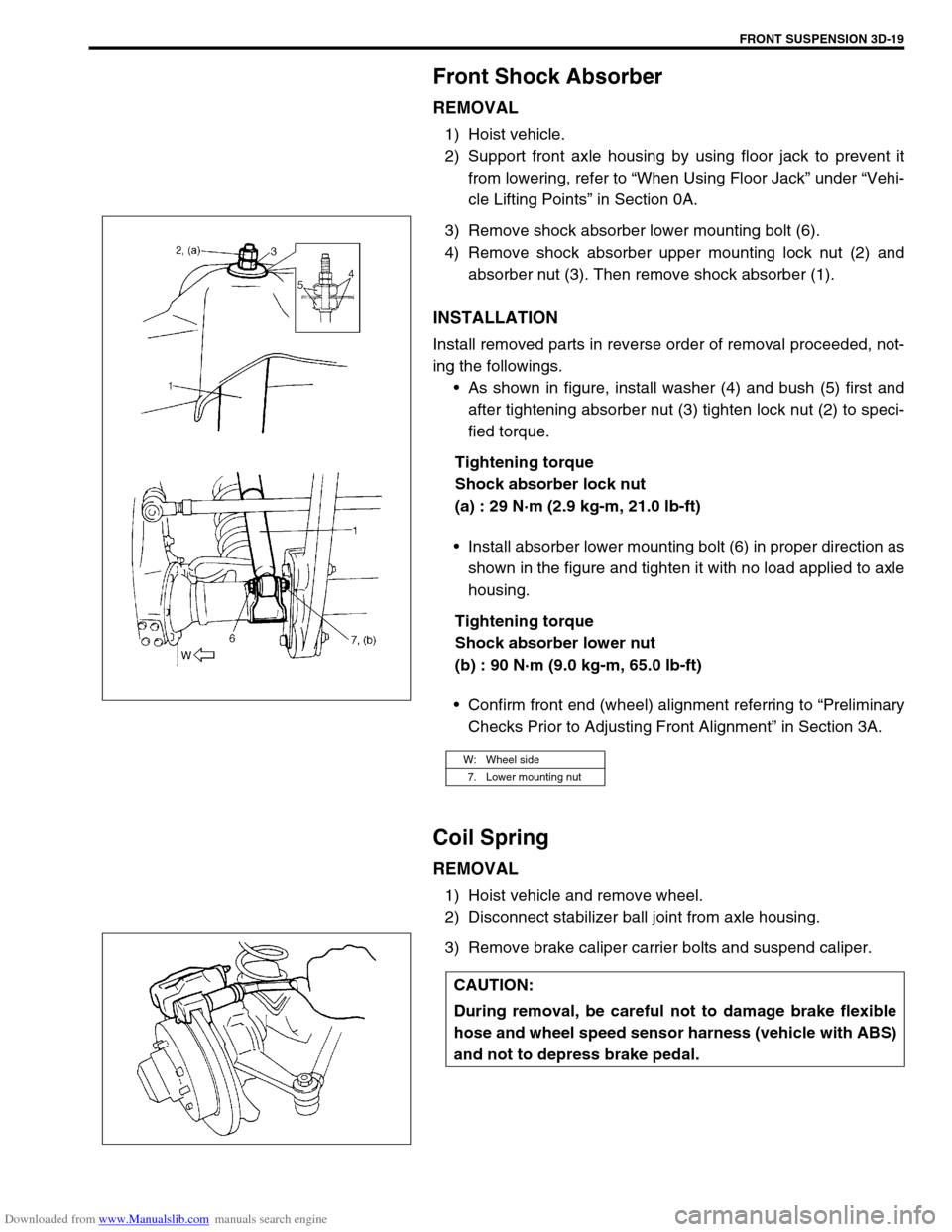
REMOVAL
1) Hoist vehicle.
2) Support front axle housing by using floor jack to prevent it
from lowering, refer to “When Using Floor Jack” under “Vehi-
cle Lifting Points” in Section 0A.
3) Remove shock absorber lower mounting bolt (6).
4) Remove shock absorber upper mounting lock nut (2) and
absorber nut (3). Then remove shock absorber (1).
INSTALLATION
Install removed parts in reverse order of removal proceeded, not-
ing the followings.
As shown in figure, install washer (4) and bush (5) first and
after tightening absorber nut (3) tighten lock nut (2) to speci-
fied torque.
Tightening torque
Shock absorber lock nut
(a) : 29 N·m (2.9 kg-m, 21.0 lb-ft)
Install absorber lower mounting bolt (6) in proper direction as
shown in the figure and tighten it with no load applied to axle
housing.
Tightening torque
Shock absorber lower nut
(b) : 90 N·m (9.0 kg-m, 65.0 lb-ft)
Confirm front end (wheel) alignment referring to “Preliminary
Checks Prior to Adjusting Front Alignment” in Section 3A.
Coil Spring
REMOVAL
1) Hoist vehicle and remove wheel.
2) Disconnect stabilizer ball joint from axle housing.
3) Remove brake caliper carrier bolts and suspend caliper.
W: Wheel side
7. Lower mounting nut
CAUTION:
During removal, be careful not to damage brake flexible
hose and wheel speed sensor harness (vehicle with ABS)
and not to depress brake pedal.