2005 SUZUKI JIMNY timing chain
[x] Cancel search: timing chainPage 380 of 687
![SUZUKI JIMNY 2005 3.G Service Workshop Manual Downloaded from www.Manualslib.com manuals search engine ENGINE GENERAL INFORMATION AND DIAGNOSIS 6-23
[D] Fig. 4 for Step 7 or 8 / [E] Fig. 5 for Step 10 / [F] Fig. 6 for Step 13
Engine diagnosis tab SUZUKI JIMNY 2005 3.G Service Workshop Manual Downloaded from www.Manualslib.com manuals search engine ENGINE GENERAL INFORMATION AND DIAGNOSIS 6-23
[D] Fig. 4 for Step 7 or 8 / [E] Fig. 5 for Step 10 / [F] Fig. 6 for Step 13
Engine diagnosis tab](/manual-img/20/7588/w960_7588-379.png)
Downloaded from www.Manualslib.com manuals search engine ENGINE GENERAL INFORMATION AND DIAGNOSIS 6-23
[D] Fig. 4 for Step 7 or 8 / [E] Fig. 5 for Step 10 / [F] Fig. 6 for Step 13
Engine diagnosis table
Perform troubleshooting referring to following table when ECM has no DTC and no abnormality found in visual
inspection and engine basic inspection previously.
Condition Possible Cause Reference Item
Hard Starting
(Engine cranks OK)Faulty ignition coil Ignition coil assembly in Section 6F.
Faulty CMP sensing rotor or CKP sensing
rotorCMP sensing rotor or CKP sensing
rotor inspection in Section 6E.
Faulty idle air control system Diagnostic Flow Table B-4
Faulty ECT sensor, TP sensor, CKP sen-
sor, CMP sensor or MAP sensorECT sensor, TP sensor, CKP sensor,
CMP sensor or MAP sensor in Sec-
tion 6E.
Fuel pressure out of specification Diagnostic Flow Table B-3
Faulty fuel injector Diagnostic Flow Table B-1
Faulty ECM Inspection of ECM and its circuit in
this section.
Malfunctioning PCV system PCV system in Section 6E.
Low compression Compression check in Section 6A1.
Improper valve lash Valve lash in Section 6A1.
Improper valve timing Timing chain and chain tensioner in
Section 6A1.
Compression leak from valve seat Valves and cylinder head in Section
6A1.
Sticky valve stem Valves and cylinder head in Section
6A1.
Weak or damaged valve springs Valves and cylinder head in Section
6A1.
Compression leak at cylinder head gasket Valves and cylinder head in Section
6A1.
Sticking or damaged piston ring Pistons, piston rings, connecting rods
and cylinders in Section 6A1.
Worn piston, ring or cylinder Pistons, piston rings, connecting rods
and cylinders in Section 6A1.
Page 482 of 687

Downloaded from www.Manualslib.com manuals search engine ENGINE MECHANICAL (M13 ENGINE) 6A1-1
6F1
6G
6H
6K
7A
7A1
7B1
7C1
7D
7E
7F
8A
8C
6A1
8E
9
9
10B
SECTION 6A1
ENGINE MECHANICAL (M13 ENGINE)
CONTENTS
General Description ......................................6A1-2
Engine ......................................................... 6A1-2
Engine Lubrication ...................................... 6A1-3
Diagnosis .......................................................6A1-4
Diagnosis Table .......................................... 6A1-4
Compression Check .................................... 6A1-4
Engine Vacuum Check ................................ 6A1-6
Oil Pressure Check ..................................... 6A1-7
Valve Lash (Clearance) ............................... 6A1-9
On-Vehicle Service......................................6A1-13
Air Cleaner Element .................................. 6A1-13
Air Cleaner Assembly ................................ 6A1-14
Knock Sensor ............................................ 6A1-14
Cylinder Head Cover ................................. 6A1-15
Throttle Body and Intake Manifold ............ 6A1-18
Exhaust Manifold ....................................... 6A1-21Oil Pan and Oil Pump Strainer .................. 6A1-24
Timing Chain Cover .................................. 6A1-28
Oil Pump ................................................... 6A1-33
Timing Chain and Chain Tensioner .......... 6A1-37
Camshaft, Tappet and Shim ..................... 6A1-42
Valves and Cylinder Head ........................ 6A1-48
Pistons, Piston Rings, Connecting
Rods and Cylinders................................... 6A1-62
Engine Mountings ..................................... 6A1-72
Unit Repair Overhaul .................................. 6A1-73
Engine Assembly ...................................... 6A1-73
Main Bearings, Crankshaft and Cylinder
Block ......................................................... 6A1-79
Required Service Material .......................... 6A1-93
Tightening Torque Specification ............... 6A1-93
Special Tool ................................................. 6A1-94
WARNING:
For vehicles equipped with Supplemental Restraint (Air Bag) System:
Service on and around the air bag system components or wiring must be performed only by an
authorized SUZUKI dealer. Refer to “Air Bag System Components and Wiring Location View” under
“General Description” in air bag system section in order to confirm whether you are performing ser-
vice on or near the air bag system components or wiring. Please observe all WARNINGS and “Ser-
vice Precautions” under “On-Vehicle Service” in air bag system section before performing service
on or around the air bag system components or wiring. Failure to follow WARNINGS could result in
unintentional activation of the system or could render the system inoperative. Either of these two
conditions may result in severe injury.
Technical service work must be started at least 90 seconds after the ignition switch is turned to the
“LOCK” position and the negative cable is disconnected from the battery. Otherwise, the system
may be activated by reserve energy in the Sensing and Diagnostic Module (SDM).
Page 483 of 687

Downloaded from www.Manualslib.com manuals search engine 6A1-2 ENGINE MECHANICAL (M13 ENGINE)
General Description
Engine
The engine is water-cooled, in line 4 cylinders, 4 stroke cycle gasoline unit with its DOHC (Double overhead
camshaft) valve mechanism arranged for “V” type valve configuration and 16 valves (4 valves / one cylinder).
The double overhead camshaft is mounted over the cylinder head; it is driven from crankshaft through timing
chain, and no push rods are provided in the valve train system.
Page 491 of 687

Downloaded from www.Manualslib.com manuals search engine 6A1-10 ENGINE MECHANICAL (M13 ENGINE)
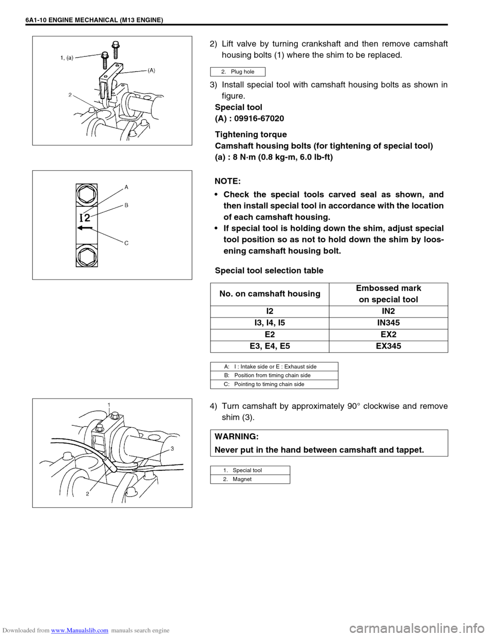
2) Lift valve by turning crankshaft and then remove camshaft
housing bolts (1) where the shim to be replaced.
3) Install special tool with camshaft housing bolts as shown in
figure.
Special tool
(A) : 09916-67020
Tightening torque
Camshaft housing bolts (for tightening of special tool)
(a) : 8 N·m (0.8 kg-m, 6.0 lb-ft)
Special tool selection table
4) Turn camshaft by approximately 90° clockwise and remove
shim (3).
2. Plug hole
NOTE:
Check the special tools carved seal as shown, and
then install special tool in accordance with the location
of each camshaft housing.
If special tool is holding down the shim, adjust special
tool position so as not to hold down the shim by loos-
ening camshaft housing bolt.
No. on camshaft housingEmbossed mark
on special tool
I2 IN2
I3, I4, I5 IN345
E2 EX2
E3, E4, E5 EX345
A: I : Intake side or E : Exhaust side
B: Position from timing chain side
C: Pointing to timing chain side
WARNING:
Never put in the hand between camshaft and tappet.
1. Special tool
2. Magnet
Page 497 of 687

Downloaded from www.Manualslib.com manuals search engine 6A1-16 ENGINE MECHANICAL (M13 ENGINE)
INSTALLATION
1) Install new spark plug hole gaskets (1) and new cylinder
head cover gasket (2) to cylinder head cover (3) as shown in
figure.
2) Remove oil, old sealant, and dust from sealing surface on
cylinder head and cover. After cleaning, apply sealant “A” to
the following point.
Cylinder head gasket (1) sealing surface area (2) as shown.
“A” : Sealant 99000-31150
Timing chain cover (1) and cylinder head (2) matching sur-
face as shown.
“A” : Sealant 99000-31150 NOTE:
Be sure to check each of these parts for deterioration or
any damage before installation and replace if found
defective.
Page 509 of 687

Downloaded from www.Manualslib.com manuals search engine 6A1-28 ENGINE MECHANICAL (M13 ENGINE)
Timing Chain Cover
REMOVAL
1) Disconnect negative cable at battery.
2) Remove A/C compressor and/or P/S pump belt (if
equipped).
3) Remove generator belt.
4) Drain engine oil.
[A] : Sealant application
amount3. Oil seal
: Apply engine oil to oil seal lip.8. Cylinder head cover
: Apply sealant 99000-31150 to the sealing
point for timing chain cover mating surface
and cylinder head gasket sealing point.
Refer to “Cylinder Head Cover Installation”.
“a” : 3 mm (0.12 in.) 4. Timing chain cover Tightening torque
: Apply sealant 99000-31140 to the mating surface
of cylinder and cylinder head.
: Apply sealant 99000-31150 to the mating surface
of timing chain cover referring to the figure of Step
1) in INSTALLATION.
“b” : 2 mm (0.08 in.) 5. Pin Do not reuse.
1. Crankshaft pulley bolt 6. Cylinder head cover gasket
2. Crankshaft pulley 7. Timing chain cover mounting bolts
Page 510 of 687

Downloaded from www.Manualslib.com manuals search engine ENGINE MECHANICAL (M13 ENGINE) 6A1-29
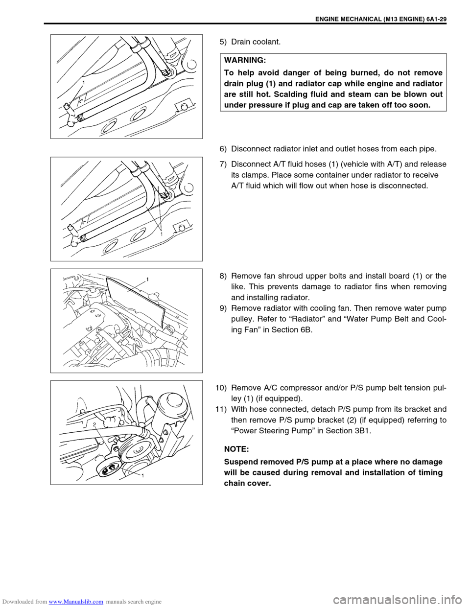
5) Drain coolant.
6) Disconnect radiator inlet and outlet hoses from each pipe.
7) Disconnect A/T fluid hoses (1) (vehicle with A/T) and release
its clamps. Place some container under radiator to receive
A/T fluid which will flow out when hose is disconnected.
8) Remove fan shroud upper bolts and install board (1) or the
like. This prevents damage to radiator fins when removing
and installing radiator.
9) Remove radiator with cooling fan. Then remove water pump
pulley. Refer to “Radiator” and “Water Pump Belt and Cool-
ing Fan” in Section 6B.
10) Remove A/C compressor and/or P/S pump belt tension pul-
ley (1) (if equipped).
11) With hose connected, detach P/S pump from its bracket and
then remove P/S pump bracket (2) (if equipped) referring to
“Power Steering Pump” in Section 3B1. WARNING:
To help avoid danger of being burned, do not remove
drain plug (1) and radiator cap while engine and radiator
are still hot. Scalding fluid and steam can be blown out
under pressure if plug and cap are taken off too soon.
NOTE:
Suspend removed P/S pump at a place where no damage
will be caused during removal and installation of timing
chain cover.
Page 511 of 687

Downloaded from www.Manualslib.com manuals search engine 6A1-30 ENGINE MECHANICAL (M13 ENGINE)
12) Remove crankshaft pulley bolt.
To lock crankshaft pulley (1), use special tool with it as
shown in figure.
Special tool
(A) : 09917-68221
13) Remove crankshaft pulley (1).
If it is hard to remove, use special tools as shown in figure.
If bolts of special tool are too long, replace them with those
of suitable length.
Special tool
(A) : 09944-36011
(B) : 09926-58010
14) Remove oil pan referring to “Oil Pan and Oil Pump Strainer”
in this section.
15) Remove cylinder head cover referring to “Cylinder Head
Cover” in this section.
16) Disconnect CMP sensor coupler (1) and release its harness
clamps.
17) Remove water outlet pipe (2).
18) Remove timing chain cover (3).
CLEANING
Clean sealing surface on timing chain cover, cylinder block
and cylinder head.
Remove oil, old sealant and dust from sealing surface.