2005 SUZUKI JIMNY transfer case
[x] Cancel search: transfer casePage 32 of 687

Downloaded from www.Manualslib.com manuals search engine MAINTENANCE AND LUBRICATION 0B-1
0A 6F1
0B
0B
6G
1A 6H
1B 6K
37A
3A 7A1
3B1 7B1
3C1 7C1
3D 7D
3E 7E
3F 7F
4A2 8A
4B 8B
8C
58D
5A 8E
5B
5C 9
5E
5E1 10
10A
610B
6-1
6A1
6A2
6A4
6B
6C
6E1
6E2
SECTION 0B
MAINTENANCE AND LUBRICATION
CONTENTS
Maintenance Schedule .................................. 0B-2
Maintenance Schedule Under Normal
Driving Conditions ........................................ 0B-2
Maintenance Recommended Under Severe
Driving Conditions ........................................ 0B-4
Maintenance Service...................................... 0B-5
Engine .......................................................... 0B-5
Drive Belt .................................................. 0B-5
Valve Lash................................................ 0B-6
Engine Oil and Filter ................................. 0B-6
Engine Coolant ......................................... 0B-8
Exhaust System ....................................... 0B-8
Ignition System ............................................. 0B-9
Spark Plugs .............................................. 0B-9
Fuel System ................................................. 0B-9
Air Cleaner Filter ...................................... 0B-9
Fuel Lines and Connections ................... 0B-10
Fuel Filter ............................................... 0B-10
Fuel Tank ............................................... 0B-10
Emission Control System ........................... 0B-10
Crankcase Ventilation Hoses and
Connections ........................................... 0B-10
PCV (Positive Crankcase Ventilation)
Valve ..................................................... 0B-11Fuel Evaporative Emission Control
System ................................................... 0B-11
Chassis and Body ...................................... 0B-11
Clutch ..................................................... 0B-11
Brake Discs and Pads ............................ 0B-11
Brake Drums and Shoes ........................ 0B-12
Brake Hoses and Pipes.......................... 0B-12
Brake Fluid ............................................. 0B-12
Parking Brake Lever and Cable ............. 0B-13
Tires/Wheels .......................................... 0B-13
Suspension System ............................... 0B-14
Propeller Shafts...................................... 0B-15
Manual Transmission Oil........................ 0B-16
Automatic Transmission Fluid ................ 0B-16
Transfer and Differential Oil ................... 0B-17
Steering System ..................................... 0B-18
Steering Knuckle Seal ............................ 0B-18
Power Steering (P/S) System
(if equipped) ........................................... 0B-19
All Hinges, Latches and Locks ............... 0B-19
Final Inspection............................................ 0B-20
Recommended Fluids and Lubricants ....... 0B-22
WARNING:
For vehicles equipped with Supplemental Restraint (Air Bag) System:
Service on and around the air bag system components or wiring must be performed only by an
authorized SUZUKI dealer. Refer to “Air Bag System Components and Wiring Location View” under
“General Description” in air bag system section in order to confirm whether you are performing ser-
vice on or near the air bag system components or wiring. Please observe all WARNINGS and “Ser-
vice Precautions” under “On-Vehicle Service” in air bag system section before performing service
on or around the air bag system components or wiring. Failure to follow WARNINGS could result in
unintentional activation of the system or could render the system inoperative. Either of these two
conditions may result in severe injury.
Technical service work must be started at least 90 seconds after the ignition switch is turned to the
“LOCK” position and the negative cable is disconnected from the battery. Otherwise, the system
may be activated by reserve energy in the Sensing and Diagnostic Module (SDM).
Page 48 of 687

Downloaded from www.Manualslib.com manuals search engine MAINTENANCE AND LUBRICATION 0B-17
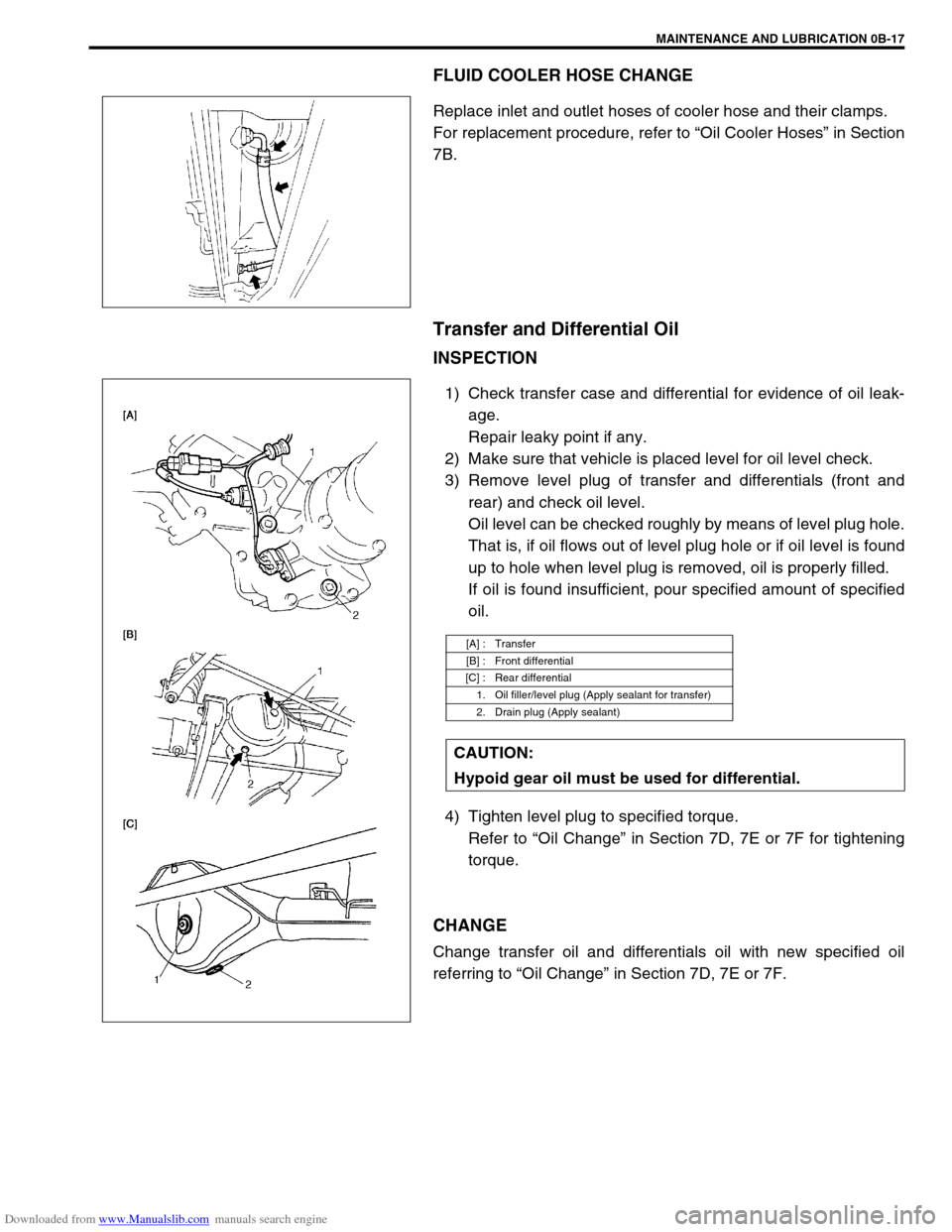
FLUID COOLER HOSE CHANGE
Replace inlet and outlet hoses of cooler hose and their clamps.
For replacement procedure, refer to “Oil Cooler Hoses” in Section
7B.
Transfer and Differential Oil
INSPECTION
1) Check transfer case and differential for evidence of oil leak-
age.
Repair leaky point if any.
2) Make sure that vehicle is placed level for oil level check.
3) Remove level plug of transfer and differentials (front and
rear) and check oil level.
Oil level can be checked roughly by means of level plug hole.
That is, if oil flows out of level plug hole or if oil level is found
up to hole when level plug is removed, oil is properly filled.
If oil is found insufficient, pour specified amount of specified
oil.
4) Tighten level plug to specified torque.
Refer to “Oil Change” in Section 7D, 7E or 7F for tightening
torque.
CHANGE
Change transfer oil and differentials oil with new specified oil
referring to “Oil Change” in Section 7D, 7E or 7F.
[A] : Transfer
[B] : Front differential
[C] : Rear differential
1. Oil filler/level plug (Apply sealant for transfer)
2. Drain plug (Apply sealant)
CAUTION:
Hypoid gear oil must be used for differential.
Page 241 of 687

Downloaded from www.Manualslib.com manuals search engine 3E-22 REAR SUSPENSION
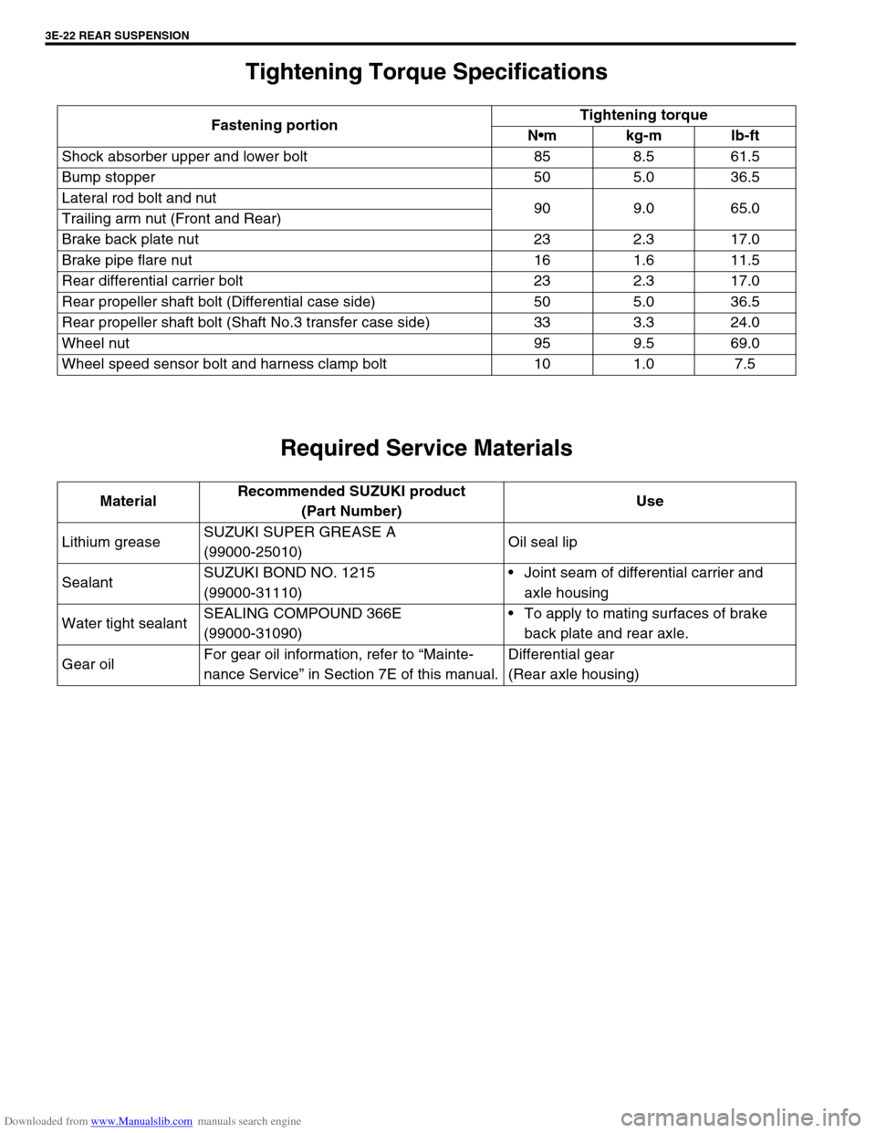
Tightening Torque Specifications
Required Service Materials
Fastening portionTightening torque
Nm kg-m lb-ft
Shock absorber upper and lower bolt 85 8.5 61.5
Bump stopper 50 5.0 36.5
Lateral rod bolt and nut
90 9.0 65.0
Trailing arm nut (Front and Rear)
Brake back plate nut 23 2.3 17.0
Brake pipe flare nut 16 1.6 11.5
Rear differential carrier bolt 23 2.3 17.0
Rear propeller shaft bolt (Differential case side) 50 5.0 36.5
Rear propeller shaft bolt (Shaft No.3 transfer case side) 33 3.3 24.0
Wheel nut 95 9.5 69.0
Wheel speed sensor bolt and harness clamp bolt 10 1.0 7.5
MaterialRecommended SUZUKI product
(Part Number)Use
Lithium greaseSUZUKI SUPER GREASE A
(99000-25010)Oil seal lip
SealantSUZUKI BOND NO. 1215
(99000-31110)Joint seam of differential carrier and
axle housing
Water tight sealantSEALING COMPOUND 366E
(99000-31090)To apply to mating surfaces of brake
back plate and rear axle.
Gear oilFor gear oil information, refer to “Mainte-
nance Service” in Section 7E of this manual.Differential gear
(Rear axle housing)
Page 257 of 687

Downloaded from www.Manualslib.com manuals search engine 4B-4 PROPELLER SHAFTS
INSTALLATION
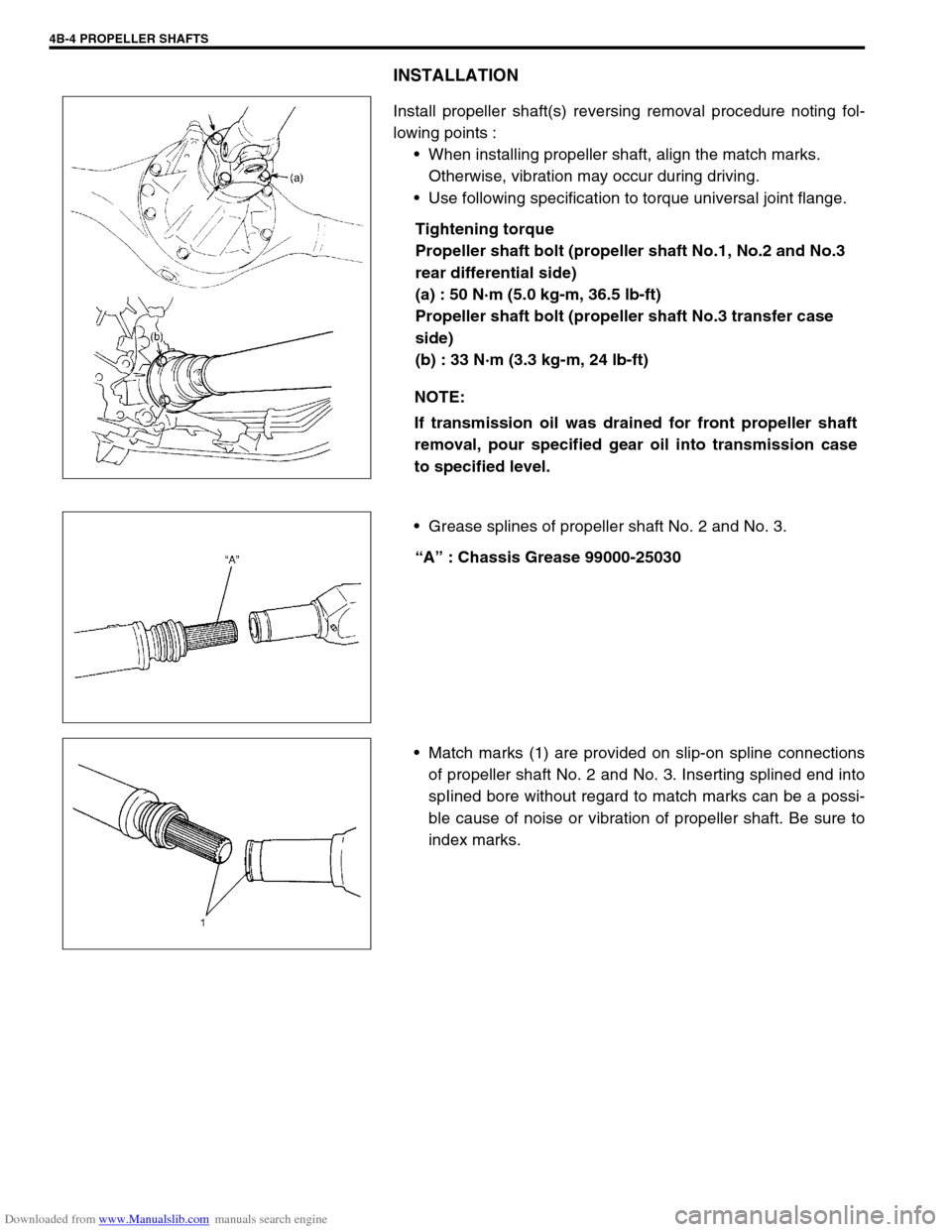
Install propeller shaft(s) reversing removal procedure noting fol-
lowing points :
When installing propeller shaft, align the match marks.
Otherwise, vibration may occur during driving.
Use following specification to torque universal joint flange.
Tightening torque
Propeller shaft bolt (propeller shaft No.1, No.2 and No.3
rear differential side)
(a) : 50 N·m (5.0 kg-m, 36.5 lb-ft)
Propeller shaft bolt (propeller shaft No.3 transfer case
side)
(b) : 33 N·m (3.3 kg-m, 24 lb-ft)
Grease splines of propeller shaft No. 2 and No. 3.
“A” : Chassis Grease 99000-25030
Match marks (1) are provided on slip-on spline connections
of propeller shaft No. 2 and No. 3. Inserting splined end into
spIined bore without regard to match marks can be a possi-
ble cause of noise or vibration of propeller shaft. Be sure to
index marks. NOTE:
If transmission oil was drained for front propeller shaft
removal, pour specified gear oil into transmission case
to specified level.
Page 260 of 687

Downloaded from www.Manualslib.com manuals search engine PROPELLER SHAFTS 4B-7
3) Insert bearing race into opposite side of shaft yoke until it is
flush with side face of shaft yoke, tapping it by a copper
hammer.
4) In the same way as Step 2) to Step 3), insert bearing races
into flange yoke.
5) Using round bar of 22 – 24 mm (0.87 in. – 0.94 in.) in diame-
ter and hammer, tap bearing races into shaft or flange yoke
until circlips can be installed in its groove on yoke bores.
6) Install 4 circlips in each groove on shaft and flange yoke
bores.
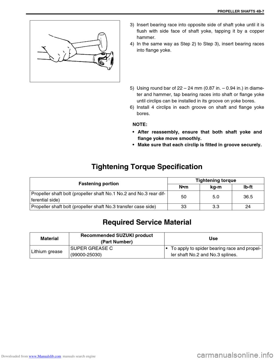
Tightening Torque Specification
Required Service Material
NOTE:
After reassembly, ensure that both shaft yoke and
flange yoke move smoothly.
Make sure that each circlip is fitted in groove securely.
Fastening portionTightening torque
Nm kg-m lb-ft
Propeller shaft bolt (propeller shaft No.1 No.2 and No.3 rear dif-
ferential side)50 5.0 36.5
Propeller shaft bolt (propeller shaft No.3 transfer case side) 33 3.3 24
MaterialRecommended SUZUKI product
(Part Number)Use
Lithium greaseSUPER GREASE C
(99000-25030)To apply to spider bearing race and propel-
ler shaft No.2 and No.3 splines.