2005 SUZUKI JIMNY body electrical
[x] Cancel search: body electricalPage 4 of 687

Downloaded from www.Manualslib.com manuals search engine TABLE OF CONTENTS
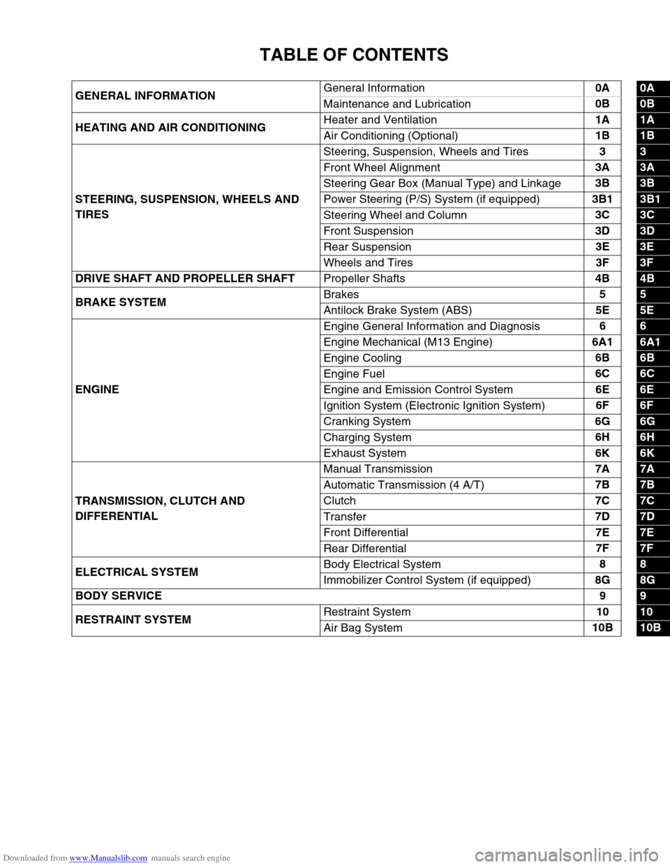
GENERAL INFORMATIONGeneral Information0A0A
Maintenance and Lubrication0B
0B
HEATING AND AIR CONDITIONINGHeater and Ventilation1A
1A
Air Conditioning (Optional)1B
1B
STEERING, SUSPENSION, WHEELS AND
TIRESSteering, Suspension, Wheels and Tires3
3
Front Wheel Alignment3A
3A
Steering Gear Box (Manual Type) and Linkage3B
3B
Power Steering (P/S) System (if equipped)3B1
3B1
Steering Wheel and Column3C
3C
Front Suspension3D
3D
Rear Suspension3E
3E
Wheels and Tires3F
3F
DRIVE SHAFT AND PROPELLER SHAFT
Propeller Shafts4B
4B
BRAKE SYSTEMBrakes5
5
Antilock Brake System (ABS)5E
5E
ENGINEEngine General Information and Diagnosis6
6
Engine Mechanical (M13 Engine)6A1
6A1
Engine Cooling6B
6B
Engine Fuel6C
6C
Engine and Emission Control System6E
6E
Ignition System (Electronic Ignition System)6F
6F
Cranking System6G
6G
Charging System6H
6H
Exhaust System6K
6K
TRANSMISSION, CLUTCH AND
DIFFERENTIALManual Transmission7A
7A
Automatic Transmission (4 A/T)7B
7B
Clutch7C
7C
Transfer7D
7D
Front Differential7E
7E
Rear Differential7F
7F
ELECTRICAL SYSTEMBody Electrical System8
8
Immobilizer Control System (if equipped)8G
8G
BODY SERVICE9
9
RESTRAINT SYSTEMRestraint System10
10
Air Bag System10B
10B
Page 6 of 687

Downloaded from www.Manualslib.com manuals search engine GENERAL INFORMATION 0A-1
0A
6F2
6G
6H
6K
7A
7A1
7B1
7C1
7D
7E
7F
8A
8B
8C
8D
8E
9
10
10A
10B
SECTION 0A
GENERAL INFORMATION
CONTENTS
How to Use This Manual .................................0A-2
Precautions......................................................0A-3
Precaution for Vehicles Equipped with a
Supplemental Restraint (Air Bag) System ..... 0A-3
Diagnosis................................................... 0A-3
Servicing and handling .............................. 0A-4
General Precautions ..................................... 0A-7
Precautions For Catalytic Converter ........... 0A-10
Precautions For Electrical Circuit Service ... 0A-10
Electrical Circuit Inspection Procedure........ 0A-13
Open circuit check ................................... 0A-13
Short circuit check (wire harness to
ground) .................................................... 0A-15
Intermittent and Poor Connection ............... 0A-15
Precaution For Installing Mobile
Communication Equipment ......................... 0A-16Identification Information ............................. 0A-17
Body Number .............................................. 0A-17
Engine Identification Number ...................... 0A-17
Transmission Identification Number............ 0A-17
Warning, Caution and Information
Labels............................................................. 0A-18
Vehicle Lifting Points ................................... 0A-19
When Using Frame Contact Hoist .............. 0A-19
When Using Floor Jack ............................... 0A-20
Abbreviations May Be Used In This
Manual............................................................ 0A-21
Abbreviations .............................................. 0A-21
Fasteners Information .................................. 0A-24
Metric Fasteners ......................................... 0A-24
Fastener Strength Identification .................. 0A-24
Standard Tightening Torque ....................... 0A-24
Page 16 of 687

Downloaded from www.Manualslib.com manuals search engine GENERAL INFORMATION 0A-11
When connecting connectors, also hold connectors and
push them together until they lock securely (a click is
heard).
When installing the wiring harness, fix it with clamps so
that no slack is left.
When installing vehicle parts, be careful so that the wir-
ing harness is not interfered with or caught by any other
part.
To avoid damage to the harness, protect its part which
may contact against a part forming a sharp angle by
winding tape or the like around it.
Be careful not to touch the electrical terminals of parts
which use microcomputers (e.g. electronic control unit
like as ECM, PCM, P/S controller, etc.). The static elec-
tricity from your body can damage these parts.
Page 20 of 687

Downloaded from www.Manualslib.com manuals search engine GENERAL INFORMATION 0A-15
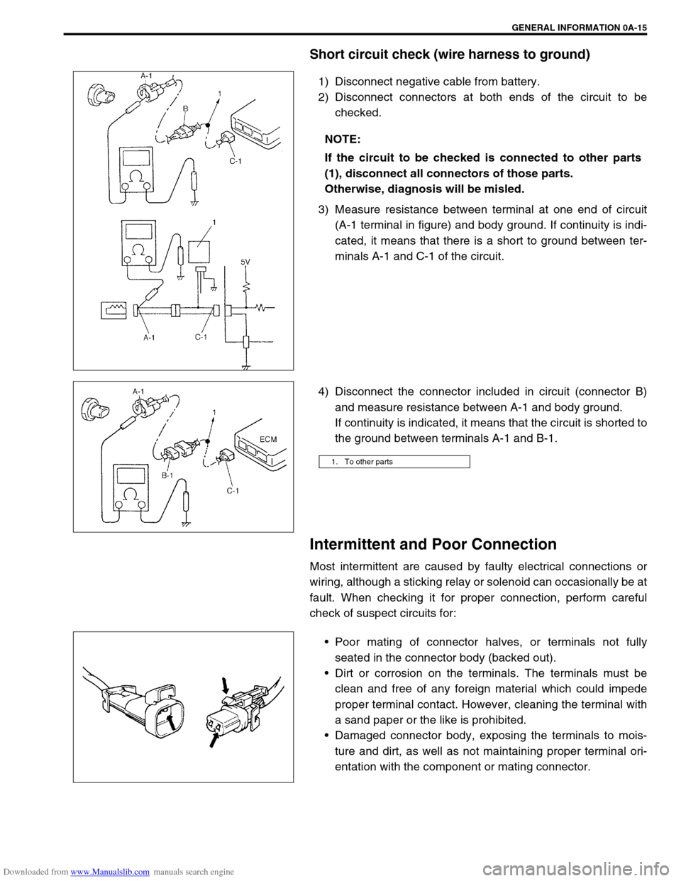
Short circuit check (wire harness to ground)
1) Disconnect negative cable from battery.
2) Disconnect connectors at both ends of the circuit to be
checked.
3) Measure resistance between terminal at one end of circuit
(A-1 terminal in figure) and body ground. If continuity is indi-
cated, it means that there is a short to ground between ter-
minals A-1 and C-1 of the circuit.
4) Disconnect the connector included in circuit (connector B)
and measure resistance between A-1 and body ground.
If continuity is indicated, it means that the circuit is shorted to
the ground between terminals A-1 and B-1.
Intermittent and Poor Connection
Most intermittent are caused by faulty electrical connections or
wiring, although a sticking relay or solenoid can occasionally be at
fault. When checking it for proper connection, perform careful
check of suspect circuits for:
Poor mating of connector halves, or terminals not fully
seated in the connector body (backed out).
Dirt or corrosion on the terminals. The terminals must be
clean and free of any foreign material which could impede
proper terminal contact. However, cleaning the terminal with
a sand paper or the like is prohibited.
Damaged connector body, exposing the terminals to mois-
ture and dirt, as well as not maintaining proper terminal ori-
entation with the component or mating connector. NOTE:
If the circuit to be checked is connected to other parts
(1), disconnect all connectors of those parts.
Otherwise, diagnosis will be misled.
1. To other parts
Page 181 of 687

Downloaded from www.Manualslib.com manuals search engine 3D-8 FRONT SUSPENSION
Diagnosis
Diagnosis Table
For description not found in the table below, refer to “Diagnosis Table” in Section 3.
4WD CONTROL SYSTEM
4WD CONTROL SYSTEM DIAGNOSTIC FLOW TABLE
Before performing the trouble diagnosis, check that the air locking hub assemblies are in good condition and
there is no air leakage from vacuum hoses and vacuum pipe. Refer to “4WD Control System Check” in this sec-
tion for air leakage.
[NOTES ON SYSTEM CIRCUIT INSPECTION]
Be sure to read “Precautions for Electrical Circuit Service” in Section 0A before circuit inspection and
observe what is written there.
For system circuit, refer to the figure of “System Circuit” in this section. Condition Possible Cause Correction
4WD Indicator light
flashingHub locking procedure error
Defective VSV2
Defective vacuum switch
Defective check valve or vacuum tank
Air leak from vacuum circuit
Clogged vacuum hose or pipe
Faulty 4WD controllerShift transfer shift control lever
2WD → 4WD once again
Replace
Replace
Replace
Check and repair
Replace
Check and replace
2WD/4WD switching
errorDefective air locking hub assembly
Abnormality in 4WD control system
Air leakage from vacuum circuit
Clogged vacuum hose or pipe
Defective check valve or vacuum tankReplace
Inspect referring to “4WD Control
System Diagnostic Flow Table”
Check and replace
Replace
Replace
Step Action Yes No
1 Check ground circuit.
1) Disconnect coupler from 4WD controller
with ignition switch OFF.
2) Check for proper connection to 4WD con-
troller at all terminals.
3) If OK, check continuity between A5 terminal
and body ground.
Is there continuity between A5 terminal and
body ground?Go to Step 2.“B” wire is open.
2 Check power circuit.
1) Disconnect coupler from 4WD controller.
2) Turn ignition switch ON.
3) Check voltage between A10 terminal and
ground.
Is it 10 – 14 V?Go to Step 3.“Y/R” circuit is open or
short.
Page 360 of 687

Downloaded from www.Manualslib.com manuals search engine ENGINE GENERAL INFORMATION AND DIAGNOSIS 6-3
General Information
Statement on Cleanliness and Care
An automobile engine is a combination of many machined, honed, polished and lapped surfaces with tolerances
that are measured in the thousands of an millimeter (ten thousands of an inch).
Accordingly, when any internal engine parts are serviced, care and cleanliness are important.
Throughout this section, it should be understood that proper cleaning and protection of machined surfaces and
friction areas is part of the repair procedure. This is considered standard shop practice even if not specifically
stated.
A liberal coating of engine oil should be applied to friction areas during assembly to protect and lubricate the
surfaces on initial operation.
Whenever valve train components, pistons, piston rings, connecting rods, rod bearings, and crankshaft jour-
nal bearings are removed for service, they should be retained in order.
At the time of installation, they should be installed in the same locations and with the same mating surfaces
as when removed.
Battery cables should be disconnected before any major work is performed on the engine.
Failure to disconnect cables may result in damage to wire harness or other electrical parts.
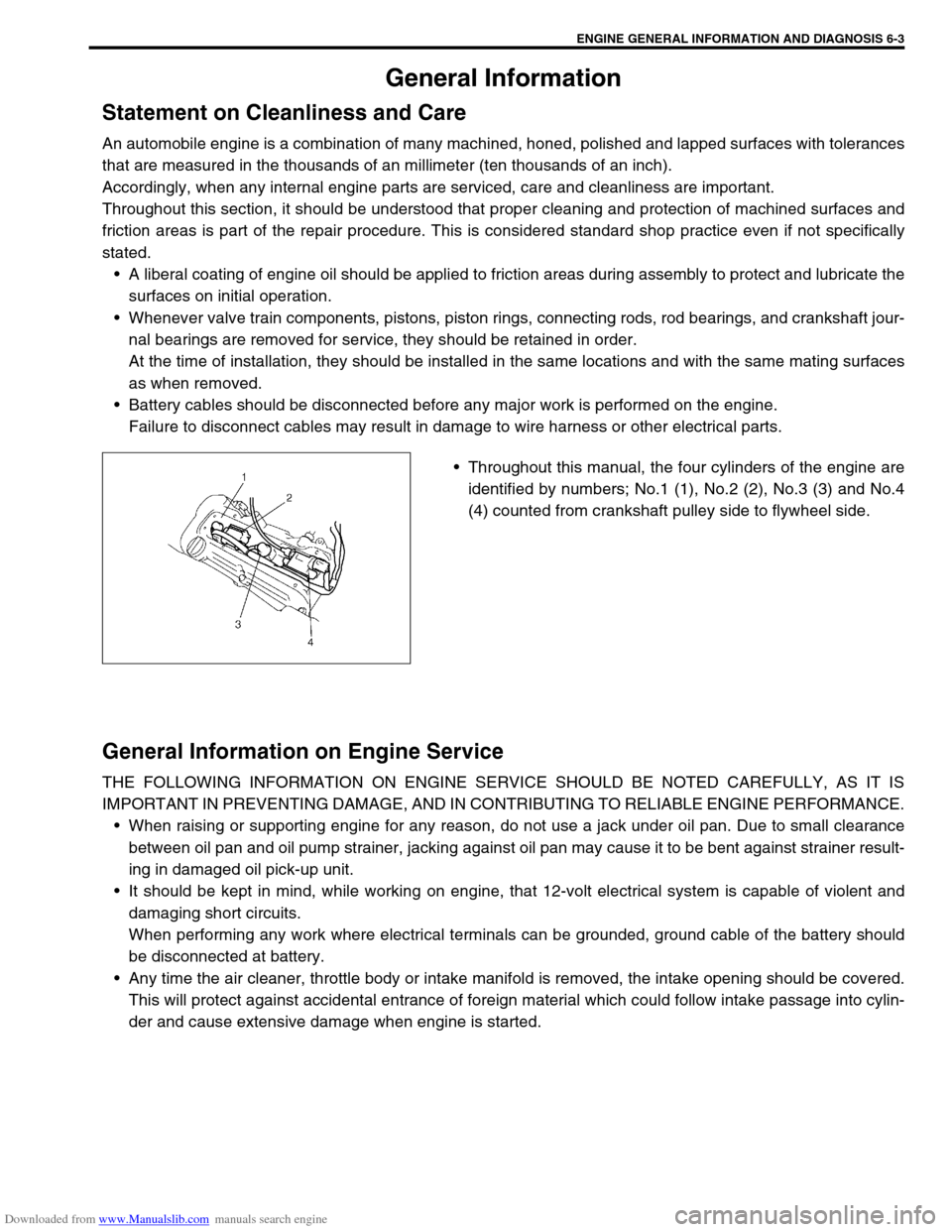
Throughout this manual, the four cylinders of the engine are
identified by numbers; No.1 (1), No.2 (2), No.3 (3) and No.4
(4) counted from crankshaft pulley side to flywheel side.
General Information on Engine Service
THE FOLLOWING INFORMATION ON ENGINE SERVICE SHOULD BE NOTED CAREFULLY, AS IT IS
IMPORTANT IN PREVENTING DAMAGE, AND IN CONTRIBUTING TO RELIABLE ENGINE PERFORMANCE.
When raising or supporting engine for any reason, do not use a jack under oil pan. Due to small clearance
between oil pan and oil pump strainer, jacking against oil pan may cause it to be bent against strainer result-
ing in damaged oil pick-up unit.
It should be kept in mind, while working on engine, that 12-volt electrical system is capable of violent and
damaging short circuits.
When performing any work where electrical terminals can be grounded, ground cable of the battery should
be disconnected at battery.
Any time the air cleaner, throttle body or intake manifold is removed, the intake opening should be covered.
This will protect against accidental entrance of foreign material which could follow intake passage into cylin-
der and cause extensive damage when engine is started.