2005 SUZUKI JIMNY pressure plate ass
[x] Cancel search: pressure plate assPage 68 of 687

Downloaded from www.Manualslib.com manuals search engine AIR CONDITIONING (OPTIONAL) 1B-7
Abnormal Noise Diagnosis
There are various types of noise, ranging from those produced in the engine compartment to those from the
passenger compartment, also from rumbling noises to whistling noises.
Abnormal noise from compressor
Abnormal noise from magnetic clutch
Abnormal noise from tubing
Abnormal noise from condenser
Condition Possible Cause Correction
During compressor
operation, a rumbling
noise is heard propor-
tional to engine revo-
lutions.Inadequate clearance in piston area (piston or
swash-plate).Repair or replace compressor as
necessary
A loud noise is heard
at a certain rpm, dis-
proportionately to
engine revolution.Loose or faulty compressor drive belt. Adjust drive belt tension, or replace
belt.
Loose compressor mounting bolts. Retighten mounting bolts.
A loud rattle is heard
at low engine rpm.Loose compressor clutch plate bolt. Retighten clutch plate bolt.
Replace compressor if it was oper-
ated in this condition for a long
time.
Condition Possible Cause Correction
A rumbling noise is
heard when compres-
sor is not operating.Worn or damaged bearings. Replace magnet clutch assembly.
A chattering noise is
heard when compres-
sor is engaged.Faulty clutch clearance (excessive). Adjust clutch clearance.
Worn clutch friction surface. Replace magnet clutch assembly.
Compressor oil leaked from lip type seal. Replace lip type seal.
Contaminating the friction surface. Replace compressor body assem-
bly.
Condition Possible Cause Correction
A droning noise is
heard inside vehicle,
but not particularly
noticeable in engine
compartment.Faulty tubing clamps. Reposition clamps or increase the
number of clamps.
Resonance caused by pulsation from variations
in refrigerant pressure.Attach a silencer to tubing, or mod-
ify its position and length.
Condition Possible Cause Correction
Considerable vibra-
tion in condenser.Resonance from condenser bracket and body. Firmly insert a silencer between
condenser bracket and body.
Page 107 of 687

Downloaded from www.Manualslib.com manuals search engine 1B-46 AIR CONDITIONING (OPTIONAL)
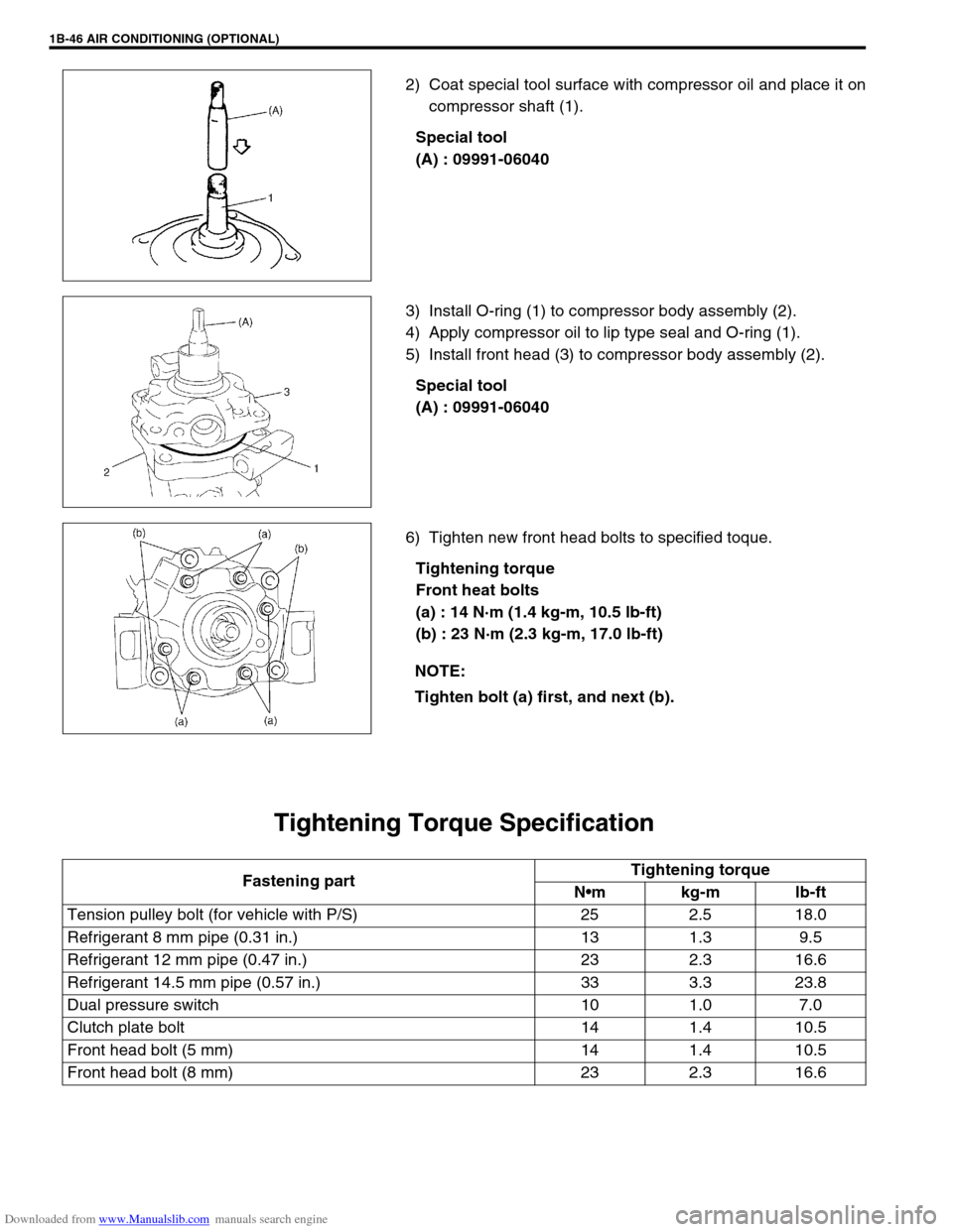
2) Coat special tool surface with compressor oil and place it on
compressor shaft (1).
Special tool
(A) : 09991-06040
3) Install O-ring (1) to compressor body assembly (2).
4) Apply compressor oil to lip type seal and O-ring (1).
5) Install front head (3) to compressor body assembly (2).
Special tool
(A) : 09991-06040
6) Tighten new front head bolts to specified toque.
Tightening torque
Front heat bolts
(a) : 14 N·m (1.4 kg-m, 10.5 lb-ft)
(b) : 23 N·m (2.3 kg-m, 17.0 lb-ft)
Tightening Torque Specification
NOTE:
Tighten bolt (a) first, and next (b).
Fastening partTightening torque
Nm kg-m lb-ft
Tension pulley bolt (for vehicle with P/S) 25 2.5 18.0
Refrigerant 8 mm pipe (0.31 in.) 13 1.3 9.5
Refrigerant 12 mm pipe (0.47 in.) 23 2.3 16.6
Refrigerant 14.5 mm pipe (0.57 in.) 33 3.3 23.8
Dual pressure switch 10 1.0 7.0
Clutch plate bolt 14 1.4 10.5
Front head bolt (5 mm) 14 1.4 10.5
Front head bolt (8 mm) 23 2.3 16.6
Page 144 of 687

Downloaded from www.Manualslib.com manuals search engine POWER STEERING (P/S) SYSTEM (If equipped) 3B1-13
5) Remove P/S pump (1) removing 3 mounting bolts (3).
DISASSEMBLY
1) Clean its exterior thoroughly.
2) With aluminum plates placed on vise first, grip pump case
with it.
3) Remove suction connector (10) and O-ring from pump body
(1).
4) Remove power steering pressure switch (3) from pump body
(1).
5) Remove relief valve (flow control valve) (2) and spring from
pump body (1).
6) Remove pump cover (11), O-ring and cam ring (6) from
pump body (1).
7) Remove vanes (9) from rotor (5).
8) Remove snap ring (8) from pump shaft (4) and pull out rotor
(5) and pulley (shaft) (4).
9) Remove side plate (7) and O-ring from pump body (1).
10) Remove oil seal from pump body (1).
INSPECTION
Pump body, cover and shaft
Check sliding surfaces of each part for wear and damage.
If any defect is found, replace pump assembly.CAUTION:
Clean couplers at intake and discharge ports com-
pletely before disconnection.
Plug ports of removed pump to prevent dust and any
foreign object from entering.
2. P/S pump bracket
1. Pulley 3. Pump cover
2. Pump body
Page 262 of 687

Downloaded from www.Manualslib.com manuals search engine BRAKES 5-1
6F1
6F2
6G
6H
6K
7A
7A1
7B1
7C1
7D
7E
5
9
10
10A
10B
9
10
10A
10B
SECTION 5
BRAKES
CONTENTS
General Description ......................................... 5-3
Diagnosis .......................................................... 5-4
Road Testing Brakes ...................................... 5-4
Brake Fluid Leaks .......................................... 5-4
Substandard or Contaminated Brake Fluid .... 5-4
Diagnosis Table ............................................. 5-5
Brake Pedal Free Height Adjustment ............. 5-8
Brake Pedal Play Check ................................ 5-8
Stop Light Switch Adjustment ........................ 5-8
Excessive Pedal Travel Check ....................... 5-9
Front Brake Disc Check ................................. 5-9
Front Brake Pad Check .................................. 5-9
Rear Brake Shoe Check .............................. 5-10
Master Cylinder and Brake Fluid Level
Check ........................................................... 5-10
Rear Drum Brake Shoe Adjustment ............. 5-11
Parking Brake Inspection and Adjustment ... 5-11
Booster Operation Check ............................. 5-12Fluid Pressure Test
(If Equipped with LSPV) ............................... 5-15
On-Vehicle Service ........................................ 5-17
Air Bleeding of Brake System ...................... 5-17
Brake Hose and Pipe Inspection.................. 5-18
Front Disc Brake .......................................... 5-19
Brake pad ................................................. 5-20
Caliper assembly...................................... 5-22
Brake Disc.................................................... 5-26
Rear Brake ................................................... 5-29
Brake drum............................................... 5-29
Brake shoe ............................................... 5-32
Wheel Cylinder............................................. 5-33
Brake back plate ...................................... 5-34
Master Cylinder .............................................. 5-36
Master Cylinder Reservoir ........................... 5-36
Master Cylinder Assembly ........................... 5-37 WARNING:
For lifting point of vehicle, refer to Section 0A.
WARNING:
For vehicles equipped with Supplement Restraint (Air Bag) System:
Service on and around the air bag system components or wiring must be performed only by an
authorized SUZUKI dealer. Refer to “Air Bag System Components and Wiring Location View” under
“General Description” in air bag system section in order to confirm whether you are performing ser-
vice on or near the air bag system components or wiring. Please observe all WARNINGS and “Ser-
vice Precautions” under “On-Vehicle Service” in air bag system section before performing service
on or around the air bag system components or wiring. Failure to follow WARNINGS could result in
unintentional activation of the system or could render the system inoperative. Either of these two
conditions may result in severe injury.
Technical service work must be started at least 90 seconds after the ignition switch is turned to the
“LOCK” position and the negative cable is disconnected from the battery. Otherwise, the system
may be activated by reserve energy in the Sensing and Diagnostic Module (SDM).
NOTE:
When inspecting and servicing vehicle equipped with ABS, be sure to refer to section 5E first.
All brake fasteners are important attaching parts in that they could affect the performance of vital
parts and systems, and/or could result in major repair expense. They must be replaced with one of
same part number or with an equivalent part if replacement becomes necessary. Do not use a
replacement part of lesser quality or substitute design. Torque values must be used as specified
during reassembly to assure proper retention of all parts. There is to be no welding as it may result
in extensive damage and weakening of the metal.
Page 480 of 687

Downloaded from www.Manualslib.com manuals search engine ENGINE GENERAL INFORMATION AND DIAGNOSIS 6-123
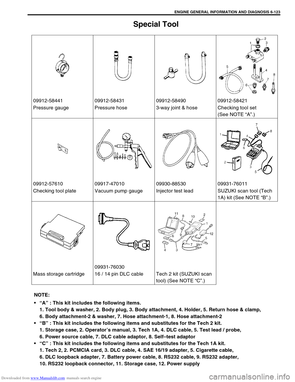
Special Tool
09912-58441 09912-58431 09912-58490 09912-58421
Pressure gauge Pressure hose 3-way joint & hose Checking tool set
(See NOTE “A”.)
09912-57610 09917-47010 09930-88530 09931-76011
Checking tool plate Vacuum pump gauge Injector test lead SUZUKI scan tool (Tech
1A) kit (See NOTE “B”.)
09931-76030
Mass storage cartridge 16 / 14 pin DLC cable Tech 2 kit (SUZUKI scan
tool) (See NOTE “C”.)
NOTE:
“A” : This kit includes the following items.
1. Tool body & washer, 2. Body plug, 3. Body attachment, 4. Holder, 5. Return hose & clamp,
6. Body attachment-2 & washer, 7. Hose attachment-1, 8. Hose attachment-2
“B” : This kit includes the following items and substitutes for the Tech 2 kit.
1. Storage case, 2. Operator’s manual, 3. Tech 1A, 4. DLC cable, 5. Test lead / probe,
6. Power source cable, 7. DLC cable adaptor, 8. Self–test adaptor
“C” : This kit includes the following items and substitutes for the Tech 1A kit.
1. Tech 2, 2. PCMCIA card, 3. DLC cable, 4. SAE 16/19 adapter, 5. Cigarette cable,
6. DLC loopback adapter, 7. Battery power cable, 8. RS232 cable, 9. RS232 adapter,
10. RS232 loopback connector, 11. Storage case, 12. Power supply
Page 538 of 687

Downloaded from www.Manualslib.com manuals search engine ENGINE MECHANICAL (M13 ENGINE) 6A1-57
Valve Springs
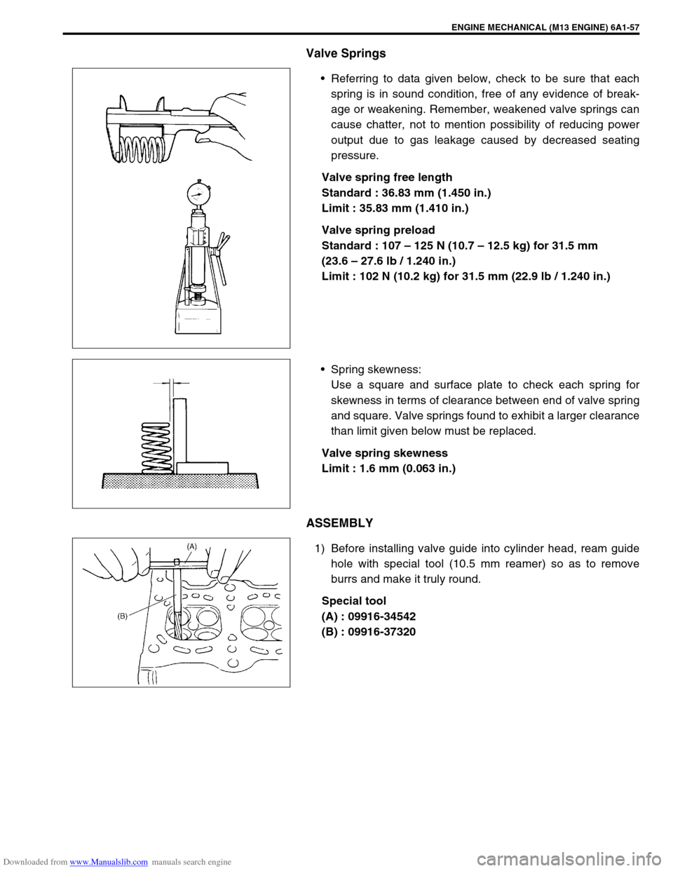
Referring to data given below, check to be sure that each
spring is in sound condition, free of any evidence of break-
age or weakening. Remember, weakened valve springs can
cause chatter, not to mention possibility of reducing power
output due to gas leakage caused by decreased seating
pressure.
Valve spring free length
Standard : 36.83 mm (1.450 in.)
Limit : 35.83 mm (1.410 in.)
Valve spring preload
Standard : 107 – 125 N (10.7 – 12.5 kg) for 31.5 mm
(23.6 – 27.6 lb / 1.240 in.)
Limit : 102 N (10.2 kg) for 31.5 mm (22.9 lb / 1.240 in.)
Spring skewness:
Use a square and surface plate to check each spring for
skewness in terms of clearance between end of valve spring
and square. Valve springs found to exhibit a larger clearance
than limit given below must be replaced.
Valve spring skewness
Limit : 1.6 mm (0.063 in.)
ASSEMBLY
1) Before installing valve guide into cylinder head, ream guide
hole with special tool (10.5 mm reamer) so as to remove
burrs and make it truly round.
Special tool
(A) : 09916-34542
(B) : 09916-37320
Page 647 of 687

Downloaded from www.Manualslib.com manuals search engine 6E-42 ENGINE AND EMISSION CONTROL SYSTEM
4) After checking vacuum, stop engine and remove PCV valve
(1).
Shake valve and listen for the rattle of check needle inside
the valve. If valve does not the rattle, replace valve.
5) After checking, remove plug and install PCV valve (1).
Special Tools
09912-57610 09912-58421 09912-58432 09912-58442
Checking tool plate Checking tool set
(See NOTE “A”.)Pressure hose Pressure gauge
09912-58490 09930-88530 09931-76011
3-way joint & hose Injector test lead SUZUKI scan tool
(Tech 1A) kit
(See NOTE “B”.)Mass storage cartridge